This is my first post . So if I'm out turn here, please be gentle.
Just got a DIY CNC machine running, and wanted to make some simple spur gears using FreeCAD. Googling led me to this thread, which thanks to the efforts of neondata & quirxi, was a major find for what I was after.
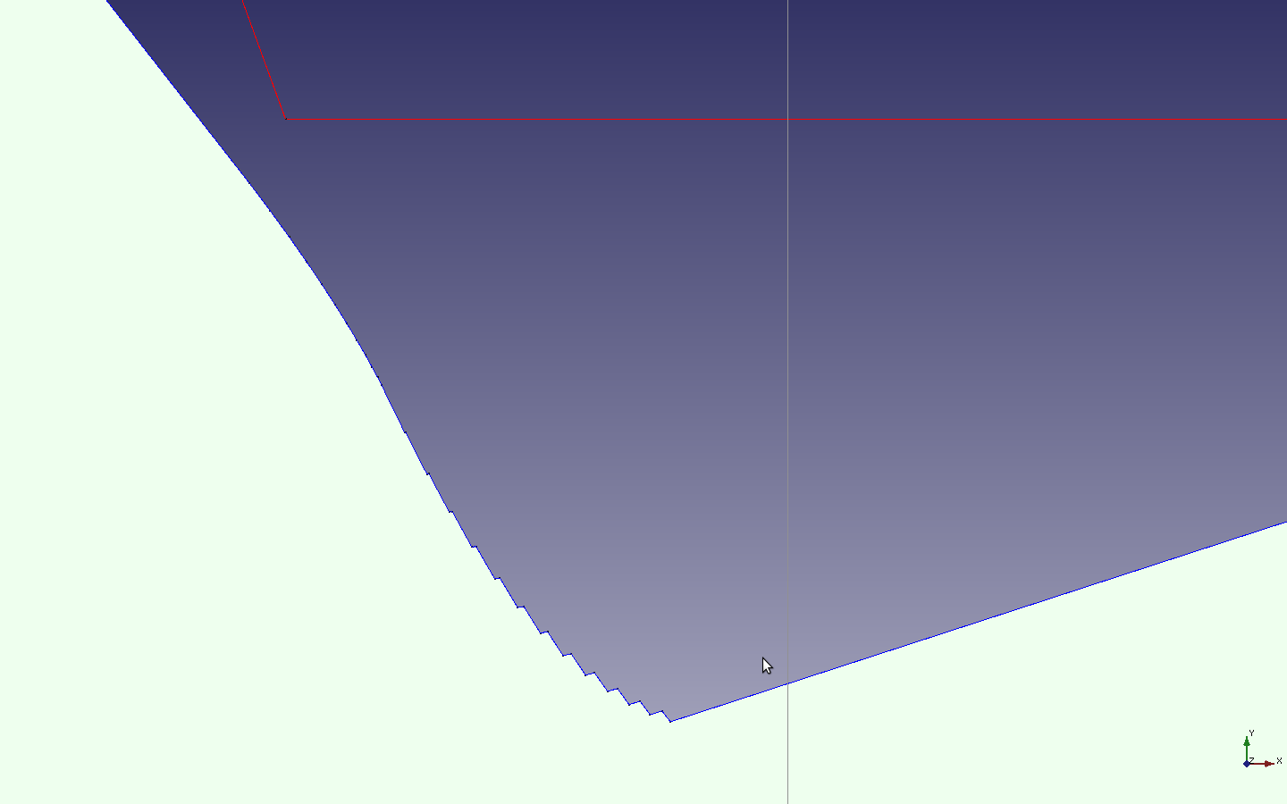
I used that code to cut several [wood] gears, and found that while they rolled well against one another, there was considerable backlash. Because everything was new to me (and I mean everything) it took a while to sort out where the "free play" was coming from. Turns out that while the Sept 7th code correctly calculated the circular tooth tickness and mirror angle, it wasn't compensating for the angular distance traveled by the involute from the base circle to the pitch circle. With this small change, the CNC machine is now cutting gears that both mesh & roll well. So again, I want to say thanks to all who made this thread possible.
And in the spirit of sharing, here's quirxi & neondata's code with changes to address the issue described above.
Code: Select all
 # Copyright 2013 Arno Wilhelm <aDOTwEDquirxiDOTnet>
    #
    #This program is free software: you can redistribute it and/or modify
    #it under the terms of the GNU General Public License as published by
    #the Free Software Foundation, either version 3 of the License, or
    #(at your option) any later version.

    #This program is distributed in the hope that it will be useful,
    #but WITHOUT ANY WARRANTY; without even the implied warranty of
    #MERCHANTABILITY or FITNESS FOR A PARTICULAR PURPOSE.  See the
    #GNU General Public License for more details.

    #You should have received a copy of the GNU General Public License
    #along with this program.  If not, see <http://www.gnu.org/licenses/>.

import Part
from FreeCAD import Base
from math import *
import FreeCAD as App, FreeCADGui as Gui, Part, Draft, math, MeshPart, Mesh
from PyQt4 import QtGui,QtCore
# default [initial] gear attributes [parameters]
N =32 # NumberTeeth
alfa = 20.0 # PressureAngle
GearHeight = 5.0 #e.g. material thickness)
#outerDiameter = (float(NumberTeeth)+2.0) * Module
outerDiameter = 60
Module = float(outerDiameter)/(float(N)+2.0)
p =  math.pi * Module #circular pitch
#Module=10.0 #The length in mm of the pitch circle diameter per tooth.
ShaftDia = 6.25 #Diameter of center hole (used for mounting shaft)
# get the angle between (0,0,0) and two points where the involute
# intersects at a given radius
def getInvoluteIntersectAngle(innerRadius, outerRadius):
    innerRadius, outerRadius = float(innerRadius), float(outerRadius)
    return (sqrt(outerRadius**2 - innerRadius**2) / (innerRadius)) - (acos(innerRadius / outerRadius))

# calculate Point on Circle in x-y plane with given radius and angle:
#              |
#  alpha       | y
# -------------|
#        x
#     sin(alpha) = y / radius => y = sin(alpha)*radius
#     cos(alpha) = x / radius => x = cos(alpha)*radius
def getPointOnCircle(radius, angle):
    x = radius * cos(radians(angle))
    y = radius * sin(radians(angle))
    return App.Vector( x, y, 0.0)

class MyGear:
    def __init__(self, obj):
        ''' Add the properties: NumberTeeth, Module, PressureAngle, GearHeight, CenterRadius, Verbose (see Property View)'''
        obj.addProperty("App::PropertyInteger","NumberTeeth","Gear","Number of teeth").NumberTeeth= 0 #will be defined later through User Input screen
        obj.addProperty("App::PropertyFloat","Module","Gear","The length in mm of the pitch circle diameter per tooth.").Module= Module
        obj.addProperty("App::PropertyAngle","PressureAngle","Gear","Pressure Angle (common values: 14.5, 20, 25 degrees)").PressureAngle= 0
        obj.addProperty("App::PropertyLength","GearHeight","Gear","Height of gear (=material thickness)").GearHeight= 0
        obj.addProperty("App::PropertyLength","CenterRadius","Gear","Radius of center hole (used for mounting shaft)").CenterRadius= 0
        obj.addProperty("App::PropertyInteger","LevelOfDetail","Gear","Level of detail of involute. The higher the number the more detail but calculation time increases.").LevelOfDetail=10
        obj.addProperty("App::PropertyBool","Verbose","Gear","Verbose mode shows data in output window.").Verbose=True
        obj.addProperty("App::PropertyBool","AutoReCalc","Gear","When 'True' View will Update /w Porperty Value Changes").AutoReCalc=False
        obj.Proxy = self

    def onChanged(self, fp, prop):
        if prop == "NumberTeeth" or prop == "Module" or prop == "PressureAngle" or prop == "GearHeight" or prop == "CenterRadius" or prop == "LevelOfDetail" or prop == "Verbose": #if one of these is changed
            AutoReCalc = fp.AutoReCalc
            if fp.AutoReCalc:
              self.execute(fp)

    # main part of script
    def execute(self, fp):
        numberTeeth        = fp.NumberTeeth
        module             = fp.Module
        pressureAngle      = fp.PressureAngle
        gearHeight         = fp.GearHeight
        centerRadius       = fp.CenterRadius
        nrPoints2Calculate = fp.LevelOfDetail
        verbose            = fp.Verbose

        # sometimes position changes (why?): remeber value and reassign at end of method:
        #print "-> Name: %s" % fp.Name
        #print "-> Placement: %s" % fp.Placement
        #print "-> Placement.Base: %s" % fp.Placement.Base
        #print "-> Placement.Rotation: %s" % fp.Placement.Rotation
        placementBase = fp.Placement.Base
        placementRotation = fp.Placement.Rotation

        if numberTeeth <= 5:
            raise Exception("Error: Number of teeth must not be <= 5 !")
        if module < 0.1 or module > 70:
            raise Exception("Error: Module out of range! Must be >= 0.1 and <= 70.")
        if gearHeight <= 0:
            raise Exception("Error: Height of gear must not be <= zero !")
        if centerRadius < 0:
            raise Exception("Error: Radius of center must not be negativ !")
        if nrPoints2Calculate < 3:
            raise Exception("Error: Level of detail must not be < 3 !")

        ## Outside Diameter
        # The outside diameter of the gear.
        # OD = (N + 2) x MOD
        outerDiameter = (numberTeeth+2.0) * module
        outerRadius = outerDiameter / 2
        ## Pitch Circle Diameter
        # The diameter of the pitch circle.
        # PCD = N x MOD
        pitchDiameter = float(numberTeeth) * module
        pitchRadius = pitchDiameter / 2
        ## Base diameter
        # The base diameter from where tooth generation starts
        baseDiameter = pitchDiameter * cos(radians(pressureAngle))
        baseRadius = baseDiameter / 2
        ## Circular Pitch
        # The distance between adjacent teeth measured along the arc at the pitch circle diameter.
        # CP = pi x MOD
        circularPitch = pi * module
        ## Circular Tooth Thickness
        # The width of a tooth measured along the arc at the pitch circle diameter.
        # CTT = CP / 2
        circularToothTickness = circularPitch / 2
        ## Addendum
        # The height of the tooth above the pitch circle diameter.
        # A = MOD
        addendum = module
        ## Whole Depth
        # The total depth of the space between adjacent teeth.
        if module >= 1 and module <=70:          #DIN 3960 (1987) 1 <= m <= 70 : hp = 2.25 *m
            wholeDepth = 2.25 * module
        elif module > 0.6 and module < 1:     #DIN 5840 (1984) 0.6 < m <= 1 : hp = 2.45 * m
            wholeDepth = 2.45 * module
        elif module >= 0.1 and module <= 0.6: #DIN 5840 (1984) 0.1 <= m <= 0.6 : hp = 2.6 * m
            wholeDepth = 2.6 * module
#        Old version:
#        if module < 1.25: # Finer than 1.25 MOD: H = 2.4 x MOD
#            wholeDepth = 2.4 * module
#        else: # 1.25 MOD and coarser: H = 2.25 x MOD
#            wholeDepth = 2.25 * module

        ## Dedendum
        # The depth of the tooth below the pitch circle diameter.
        # D = H - A
        dedendum = wholeDepth - addendum
        ## Root Diameter
        # Diameter of bottom of tooth spaces. Comprises clearence
        rootDiameter = pitchDiameter - 2*dedendum
        rootRadius = rootDiameter / 2

        if centerRadius > rootRadius + 1:
            raise Exception("Error: Diameter of hole in center may not be greater then gear itself!")

        if verbose:
            print "\nNumber Teeth:  %s" % numberTeeth
            print "Module:          %s" % module
            print "Pressure Angle:  %s" % pressureAngle

            print "Diametral Pitch: %s" % (25.4 / module)
            print "Circular Pitch:  %s" % circularPitch
            print "Circular Tooth Thickness: %s" % circularToothTickness

            print "Whole Depth:     %s" % wholeDepth
            print "Addendum:        %s" % addendum
            print "Dedendum:        %s" % dedendum

            print "Outer Diameter:  %s" % outerDiameter
            print "Pitch Diameter:  %s" % pitchDiameter
            print "Base Diameter:   %s" % baseDiameter
            print "Root Diameter:   %s" % rootDiameter
            print "Outer Radius:    %s" % outerRadius
            print "Pitch Radius:    %s" % pitchRadius
            print "Base Radius:     %s" % baseRadius
            print "Root Radius:     %s" % rootRadius

        # draw outer circle
        outerCircle = Part.Circle()
        outerCircle.Radius = outerRadius
        outerCircleObj = fp.Document.addObject("Part::Feature", "Outer Circle")
        outerCircleObj.ViewObject.LineWidth = 1.0
        outerCircleObj.ViewObject.LineColor = (0.00,0.00,1.00)
        outerCircleObj.Shape = outerCircle.toShape()
        outerCircleObj.ViewObject.hide()

        # draw pitch circle
        pitchCircle = Part.Circle()
        pitchCircle.Radius = pitchRadius
        pitchCircleObj = fp.Document.addObject("Part::Feature", "Pitch Circle")
        pitchCircleObj.ViewObject.LineWidth = 1.0
        pitchCircleObj.ViewObject.LineColor = (0.00,0.00,1.00)
        pitchCircleObj.Shape = pitchCircle.toShape()
        pitchCircleObj.ViewObject.hide()

        # draw base circle
        baseCircle = Part.Circle()
        baseCircle.Radius = baseRadius
        baseCircleObj = fp.Document.addObject("Part::Feature", "Base Circle")
        baseCircleObj.ViewObject.LineWidth = 1.0
        baseCircleObj.ViewObject.LineColor = (0.00,0.00,1.00)
        baseCircleObj.Shape = baseCircle.toShape()
        baseCircleObj.ViewObject.hide()

        # draw root circle
        rootCircle = Part.Circle()
        rootCircle.Radius = rootRadius
        rootCircleObj = fp.Document.addObject("Part::Feature", "Root Circle")
        rootCircleObj.ViewObject.LineWidth = 1.0
        rootCircleObj.ViewObject.LineColor = (0.00,0.00,1.00)
        rootCircleObj.Shape = rootCircle.toShape()
        rootCircleObj.ViewObject.hide()

        # draw crosshair
        verticalCross=Part.Line()
        verticalCross.StartPoint=(0.0,-(outerRadius+10),0.0)
        verticalCross.EndPoint=(0.0,(outerRadius+10),0.0)
        verticalCrossObj=fp.Document.addObject("Part::Feature","Vertical Cross")
        verticalCrossObj.ViewObject.LineWidth = 0.5
        verticalCrossObj.ViewObject.LineColor = (0.57,0.57,0.57)
        verticalCrossObj.Shape = verticalCross.toShape()
        verticalCrossObj.ViewObject.hide()

        horizontalCross=Part.Line()
        horizontalCross.StartPoint=(-(outerRadius+10),0.0, 0.0,)
        horizontalCross.EndPoint=((outerRadius+10),0.0, 0.0,)
        horizontalCrossObj=fp.Document.addObject("Part::Feature","Horizontal Cross")
        horizontalCrossObj.ViewObject.LineWidth = 0.5
        horizontalCrossObj.ViewObject.LineColor = (0.57,0.57,0.57)
        horizontalCrossObj.Shape = horizontalCross.toShape()
        horizontalCrossObj.ViewObject.hide()

        # calculate angle of involute curve from base circle to outer circle
        toothFlankAngle = (sqrt( outerRadius*outerRadius - baseRadius*baseRadius )) / baseRadius
        if verbose: print "Angel of Tooth Flank: %s" % toothFlankAngle

        # divide the toothFlankAngle trough the number of points that should be
        # calculated along the involute curve in order to construct this curve.
        # The higher the number of points the smaller the single angle and the more
        # detailed the resulting curve
        singleAngle = toothFlankAngle / float(nrPoints2Calculate) #measured in radians

        # calculate x and y coordinate for each point along the involute curve where the
        # angle = [0 : nrPoints2Calculate]*singleAngle <= toothFlankAngle
        # make list of points
        pointList = list()
        lineList = list()
        if verbose: print "Base Circle Circumfence: %s" % (2*baseRadius*pi)
        for step in range(0, nrPoints2Calculate+1):
            # angle for current point
            angle = singleAngle * step
            # length from tangent point to involute point
            s = baseRadius*angle
            # calculate point on base circle where involute is tangent to the circle
            xtCoord = baseRadius * cos(angle)
            ytCoord = baseRadius * sin(angle)
            # calculate point on involute curve
            xiCoord = xtCoord + s * sin(angle)
            yiCoord = ytCoord - s * cos(angle)
            pointList.append( App.Vector( float(xiCoord), float(yiCoord), 0.0 ) )
            if len(pointList) > 1:
                line = Part.Line(pointList[-2], pointList[-1])
                lineList.append(line.toShape())

        involuteWire = Part.Wire(lineList)
        # draw line from end of involute to root cirlce.
        # This line goes from endpoint of involute (on base circle) to root circle
        # in the direction towards the center of the gear and provides clearence.
         # either: rootLine = Part.Line(pointList[0], getPointOnCircle(rootRadius, 0) )
         # or ma is simple because endpoint of involute lies on x-axis :O :
        rootLine = Part.Line(App.Vector(rootRadius, 0), App.Vector(baseRadius, 0) )
        rootLineWire=Part.Wire(rootLine.toShape().Edges)
        involute = Part.Wire([rootLineWire, involuteWire])

        # calculate mirror line for single tooth flank
        # mirror line goes trough (0,0,0) and the point on the pitch circle where
        # lenght along pitch circle = circularToothTickness/2
        # calculate angle:
        # Attention: since the involute starts at the base circle at angle 0 but
        # the angle of mirrorline is calculated from point were involute intersects
        # pitch circle we have to add this angle to the mirror angle.
            # Die Laenge b eines Kreisbogens mit dem Mittelpunktswinkel alpha im Winkelmass
            # und dem Radius r lewsst sich durch folgende Formel berechnen:
            # b = pi * r (alpha\180) => alpha = (b * 180) / (pi * r)
            # mirrorAngle = ( (circularToothTickness/2.0) * 180.0) / ( pi * pitchRadius )
            # OR MUCH EASIER :): mirrorAngle = (360.0 / numberTeeth) / 4.0
        toothAngle = 360.0 / numberTeeth
        baseToPitchAngle = getInvoluteIntersectAngle( baseRadius, pitchRadius )
# my way for deriving baseToPitchAngle
        #First, for the given pressure angle, find the tangental length of string needed to span the
        #distance from the base circle to the pitch circle
        StrLen =  sqrt(pitchRadius**2- (pitchRadius*cos(radians(pressureAngle)))**2)
        #print "String Lenght = %s" %StrLen
        #Cicumference formula; C = 2*Pi*r; or Distance along a circle is d = radius*angle(in radians)
        #=> angle = d/radius; So in this case:
        baseToPitchAngle = degrees(StrLen/baseRadius)- pressureAngle

        # TODO: is this baseToPitchAngle in degree or radians ?! Is calculation right??
        #mirrorAngle = (toothAngle/4.0) + degrees(baseToPitchAngle)
        mirrorAngle = toothAngle/4.0
        #mirrorAngle = (toothAngle/4.0) + baseToPitchAngle
#        print "Method 1 mirrorAngle: %s" % mirrorAngle
#        mirrorAngle = ( (circularToothTickness/2.0) * 180.0) / ( pi * pitchRadius )
#        print "Method 2 mirrorAngle: %s" % mirrorAngle
        MymirrorPoint = getPointOnCircle(outerRadius, mirrorAngle+(2*baseToPitchAngle))
        mirrorPoint = getPointOnCircle(outerRadius, mirrorAngle)

        if verbose:
            MrAnglCalcTT = (pitchRadius)*radians(2*mirrorAngle)
            print "Angle single tooth occupies: %s Degs" % toothAngle
            print "Angle between involute on base circle and involute on pitch circle: %s ?!" % baseToPitchAngle
            print "Mirror angle: %s" % mirrorAngle
            print "Mirror point: %s" % mirrorPoint
            print "Tooth Thickness based on Mirror angle : %s" % MrAnglCalcTT
            offsetAngle = baseToPitchAngle
            MAxCoord = outerRadius * cos(radians(mirrorAngle+offsetAngle))
            MAyCoord = outerRadius * sin(radians(mirrorAngle+offsetAngle))
            Mirrorangle=Part.Line()
            Mirrorangle.StartPoint=(0.0,0.0, 0.0,)
            Mirrorangle.EndPoint=(float(MAxCoord), float(MAyCoord), 0.0,)
            MirrorangleObj=fp.Document.addObject("Part::Feature","Mirror Angle")
            MirrorangleObj.ViewObject.LineWidth = 0.5
            MirrorangleObj.ViewObject.LineColor = (0.57,0.57,0.57)
            MirrorangleObj.Shape = Mirrorangle.toShape()
            MirrorangleObj.ViewObject.hide()
            StrtPoint = getPointOnCircle(outerRadius, offsetAngle)
            CntrPoint = getPointOnCircle(0, 0)
            EndPoint  = getPointOnCircle(outerRadius, 2*(mirrorAngle)+offsetAngle)
            CTTLine = Part.makePolygon([StrtPoint,CntrPoint, EndPoint])
            CTTLineObj=fp.Document.addObject("Part::Feature","Circular Tooth Thickness")
            CTTLineObj.ViewObject.LineWidth = 0.5
            CTTLineObj.ViewObject.LineColor = (0.57,0.57,0.57)
            CTTLineObj.Shape = CTTLine
            CTTLineObj.ViewObject.hide()
        # mirror involute around line in middle of tooth (=mirrorLine)
        # calculate the transform matrix for reflection around arbitrary line through (0,0,0)
        # see: http://www.scibuff.com/2009/06/22/reflection-matrix/
        # see: http://answers.yahoo.com/question/index?qid=20110628095842AARdMwL
        # see: http://www.geom.uiuc.edu/docs/reference/CRC-formulas/node9.html
#        oans = float(cos(2*radians(mirrorAngle)))
#        zwoa = float(sin(2*radians(mirrorAngle)))
#        drai = float(sin(2*radians(mirrorAngle)))
#        via =  float(-(cos(2*radians(mirrorAngle))))
# use my mirrorAngle+(2*baseToPitchAngle to work out the new mirror matrix
        oans = float(cos(2*radians(mirrorAngle+(1*baseToPitchAngle))))
        zwoa = float(sin(2*radians(mirrorAngle+(1*baseToPitchAngle))))
        drai = float(sin(2*radians(mirrorAngle+(1*baseToPitchAngle))))
        via =  float(-(cos(2*radians(mirrorAngle+(1*baseToPitchAngle)))))

        mirrorMatrix = Base.Matrix(oans,zwoa,0.0,0.0,drai,via,0.0,0.0,0.0,0.0,0.0,0.0,0.0,0.0,0.0,0.0)
        if verbose: print "mirrorMatrix: %s" % mirrorMatrix
        mirrorInvolute = involute.transformGeometry(mirrorMatrix)
        # Since the vertexes in the mirrored involute are reversed in the list of vertices ->
        # -> in order to join them successfully with the other wires we have to reverse them:
        edgeList = []
        for i in xrange(len(mirrorInvolute.Vertexes)-1, -1, -1):
            if i < (len(mirrorInvolute.Vertexes)-1):
                edge = Part.Line(mirrorInvolute.Vertexes[i+1].Point, mirrorInvolute.Vertexes[i].Point)
                edgeList.append(edge.toShape())
        reversedMirroredInvolute = Part.Wire(edgeList)

        # draw arc between two involutes on outer circle
        outerArc = Part.Arc(pointList[-1],mirrorPoint, mirrorInvolute.Edges[-1].Vertexes[-1].Point)
        outerArcWire = Part.Wire( outerArc.toShape().Edges )

        # draw arc between two teeth on root circle
        firstPoint = reversedMirroredInvolute.Edges[-1].Vertexes[-1].Point
        middlePoint = getPointOnCircle(rootRadius, ((toothAngle/4.0)*3.0))
        endPoint = getPointOnCircle(rootRadius, toothAngle)
        #middlePoint = getPointOnCircle(rootRadius, (((toothAngle/4.0)*3.0)+baseToPitchAngle))
        #endPoint = getPointOnCircle(rootRadius, (toothAngle+baseToPitchAngle))
        innerArc = Part.Arc(firstPoint, middlePoint, endPoint)
        innerArcWire = Part.Wire( innerArc.toShape().Edges )

        # join single wires in order to get whole tooth
        wholeTooth = Part.Wire([involute, outerArcWire, reversedMirroredInvolute, innerArcWire])
        # Show wholeTooth as a wire [I added this]
        wholeToothObj=fp.Document.addObject("Part::Feature","Whole Tooth Wire")
        wholeToothObj.ViewObject.LineWidth = 0.5
        wholeToothObj.ViewObject.LineColor = (0.57,0.57,0.57)
        wholeToothObj.Shape = wholeTooth
        wholeToothObj.ViewObject.hide()
#        MymirrorPointPart = Part.Point(MymirrorPoint)
#        faceEdge = Part.makeLine(MymirrorPoint,MymirrorPoint+Base.Vector(0.0,0.0,1.0))
#        MymirrorPointObj=fp.Document.addObject("Part::Feature","My MirrorPoint")
#        MymirrorPointObj.ViewObject.LineWidth = 1.5
#        MymirrorPointObj.ViewObject.LineColor = (0.57,0.57,0.57)
#        MymirrorPointObj.Shape = faceEdge #MymirrorPointPart


        # copy tooth numberTeeth times and rotate copies around circle
        #if verbose:
        #    print "wholeTooth[0]: %s" % wholeTooth.Edges[0].Vertexes[0].Point
        #    print "wholeTooth[-1]: %s" % wholeTooth.Edges[-1].Vertexes[-1].Point
        gearWire = wholeTooth.copy()
        for step in range(1, numberTeeth):
            toothWire = wholeTooth.copy()
            toothWire.rotate(App.Vector(0.0,0.0,0.0), App.Vector(0.0,0.0,1.0), step*toothAngle)
            #print "toothWire[0]: %s toothWire[-1]: %s" % (toothWire.Edges[0].Vertexes[0].Point, toothWire.Edges[-1].Vertexes[-1].Point)
            ## fuse() method had problems closing the shape !!??
                # gearWire = gearWire.fuse(toothWire)
            gearWire = Part.Wire([gearWire,toothWire])
            #print "gearWire[0]:  %s  gearWire[-1]: %s" %  (gearWire.Edges[0].Vertexes[0].Point , gearWire.Edges[-1].Vertexes[-1].Point)

        # extrude 2D shape into 3d object
        gearFace = Part.Face(gearWire)
        ## cut hole in center of gear for mounting shaft
        if centerRadius > 0:
            centerHole = Part.Circle()
            centerHole.Radius = float(centerRadius)
            centerHoleShape = centerHole.toShape()
            centerHoleFace = Part.Face(Part.Wire(centerHoleShape.Edges))
            gearFace = gearFace.cut(centerHoleFace)

        gearShell = Part.Shell(gearFace.Faces)
        extrudedGear = gearShell.extrude(Base.Vector(0.0,0.0,gearHeight))
        fp.Shape = extrudedGear

        # sometimes position changes (why?): reset positon to remembered value:
        fp.Placement.Base = placementBase
        fp.Placement.Rotation = placementRotation

def makeGear(paramlst):
    NumberTeeth = paramlst[0]
    PressureAngle = paramlst[1]
    GearHeight = paramlst[2]
    CenterRadius = paramlst[3]/2
    LevelOfDetail = paramlst[4]
    Module = paramlst[5]

    doc = FreeCAD.activeDocument()
    if doc == None:
        doc = FreeCAD.newDocument("Gear")
    gear=doc.addObject("Part::FeaturePython","Gear") #add object to document
    gear.Label = "3DGearPart"
    MyGear(gear)
    gear.NumberTeeth = NumberTeeth
    gear.PressureAngle = PressureAngle
    gear.Module = Module
    gear.GearHeight = GearHeight
    gear.CenterRadius = CenterRadius
    gear.LevelOfDetail = LevelOfDetail
    gear.AutoReCalc = True
    gear.ViewObject.Proxy=0
    doc.recompute()
    Gui.SendMsgToActiveView("ViewFit") # center gear in view ...

def proceed():
#    try:
        InitParam = []
        InitParam = ExtractUsrInput()
        makeGear(InitParam)
#    except:
#        print "\nExtractUsrInput Code Failed"
#        hide()

def ExtractUsrInput():
#    try:
     N      = int  (l[0].text())       # Number of teeth (N)
#     NumberTeeth=N
#     m      = float(l[1].text())       #module
     p      = float(l[1].text())       # Circular pitch (p)
     m = p/math.pi
        #outerDiameter = p
     alfa   = float(l[2].text())       # Pressure angle (alfa)
#     PressureAngle=alfa
     y      = float(l[3].text())       # Tooth hight factor (y)      standard value y<1 for gear drives y>1 for Gear pumps
#    m      = p/math.pi                #standard value 0.06, 0.12, 0.25, 0.5, 1, 2, 4, 8, 16, 32, 60 (polish norm)
     c      = float(l[4].text())*m     # Tooth clearance (c)          standard value 0,1*m - 0,3*m
     j      = float(l[5].text())*m     # Tooth lateral clearance (j)  standard value 0,015 - 0,04*m
     width  = float(l[6].text())       #gear width; i.e. material thickness)
     InvPts = int  (l[7].text())       #resolution, # of interpolated points
     SD      = float(l[8].text())      #Shaft [i.e. Axle] Diameter
#    except:
#        FreeCAD.Console.PrintError("Wrong input! Only numbers allowed...\n")

     h  = 2*y*m+c           #tooth height
     d  = N*m               #pitch diameter
     rp_sqr = d*d/4         # sqr pitch radius
     df = d - h - c         #root diameter             #df=d-2hf where and hf=y*m+c
     da = d + h - c         #addendum diameter         #da=d+2ha where ha=y*m
     ra_sqr = da*da/4       # sqr addendum radius
     db = d * math.cos(math.radians(alfa)) #base diameter for involute

    #Base circle  radius, first angle, second angle
#    addendumCircle = MakeCircle("AddendumCircle", da/2, 0.0, 0.0)   #Addendum circle
#    pitchCircle    = MakeCircle("PitchCircle",     d/2, 0.0, 0.0)   #Pitch circle

     FreeCAD.Console.PrintError("\n\nNew Gear Parameters....\n\n")
     FreeCAD.Console.PrintError("tooth height       "+str(h) + "..\n")
     FreeCAD.Console.PrintError("tooth thickness [CTT=CP/2] "+str(p/2) + "..\n")
     FreeCAD.Console.PrintError("addendum diameter  "+str(da)+ "..\n")
     FreeCAD.Console.PrintError("pitch diameter     "+str(d) + "..\n")
     FreeCAD.Console.PrintError("base diameter      "+str(db)+ "..\n")
     FreeCAD.Console.PrintError("root diameter      "+str(df)+ "..\n")
     hide()
     InitParam = []
     InitParam.append(N)
     InitParam.append(alfa)
     InitParam.append(width)
     InitParam.append(SD)
     InitParam.append(InvPts)
     InitParam.append(m)
     return InitParam

def hide():
    dialog.hide()

# Now Define User Input GUI
GuiSize  = [200,450]
GuiTitle = "Metric Gear Params"

l = []  # Array to transfer parameters to the process
F =     [["Number of teeth (N)"         ,   "%s" % N]]
F.append(["Circular Pitch [module X Pi]"          ,"%s" % p])
F.append(["Pressure angle (alfa)"       ,  "%s" % alfa])
F.append(["Tooth height factor (y)"     ,  "1.0"])
F.append(["Tooth clearance (c)"         ,  "0.2"])
F.append(["Tooth lateral clearance (j)" , "0.04"])
F.append(["Gear width"                  ,  "%s" % GearHeight])
F.append(["# of points in involute"     ,   "10"])
F.append(["Center Hole [Shaft] Diameter",   "%s" %ShaftDia])
dialog = QtGui.QDialog()
dialog.resize(GuiSize[0],GuiSize[1])
dialog.setWindowTitle(GuiTitle)
la = QtGui.QVBoxLayout(dialog)

for field in range(len(F)):

  la.addWidget(QtGui.QLabel(F[field][0]))
  l.append( QtGui.QLineEdit(F[field][1]) )
  la.addWidget(l[field])

c1 = QtGui.QCheckBox("Create as a Mesh")
la.addWidget(c1)
e1 = QtGui.QLabel("(for faster rendering)")
e1.setFont(QtGui.QFont("Times",8,True))
la.addWidget(e1)

okbox = QtGui.QDialogButtonBox(dialog)
okbox.setOrientation(QtCore.Qt.Horizontal)
okbox.setStandardButtons(QtGui.QDialogButtonBox.Cancel|QtGui.QDialogButtonBox.Ok)
la.addWidget(okbox)
QtCore.QObject.connect(okbox, QtCore.SIGNAL("accepted()"), proceed)
QtCore.QObject.connect(okbox, QtCore.SIGNAL("rejected()"), hide)
QtCore.QMetaObject.connectSlotsByName(dialog)
dialog.show()
#if __name__ == "__main__": #feature will be generated after macro execution
#    confirmGearParams()
#    makeGear()
PS: This is still a work in progress, so some of the parameter settings found on the setup screen actually have no effect on the rendered gear