
Take a look in the directory containing that file. Look for one with the correct name and a file extension of .FCStd1. This would be a backup before your accidental over-write. It's kind of a long shot but worth a look...pa4tim wrote:I , by accident, over-written the file.
recognizing faults
Forum rules
and Helpful information
and Helpful information
IMPORTANT: Please click here and read this first, before asking for help
Also, be nice to others! Read the FreeCAD code of conduct!
Also, be nice to others! Read the FreeCAD code of conduct!
Re: recognizing faults
Re: recognizing faults
Hereby the result of a lot of sweat and blood.
This is something I want to print with a K8200 using repetier and slic3r (It came with the printer)
I tried the mesh workbank but I was glad I first made a backup file. Just pressing buttons without understanding them gives rather curious results.
I started with a new fresh design instead of trying to repair the old. That keeps it more clean. The problem are the constrains. I made a sketch with around 60 contrains. I then changed something and the computer was busy for 15 minutes but it did not crash. (happened only once with 014, so I'm happy) So I then made a sketch, padded it, than the next sketch etc. That worked well. At the end I noticed I had made a mistake in the first sketch. The footprint was >20 cm. I changed the sketch and it nicely changed every step. (iI wish there was a tool that finds non-contrains) Great, I realy start to like Freecad..
I now made it rather straight forward. No nice rounded edges etc. That will come if the base is good, The bottom is the thing that holds the PCB's. Mid are the sides of the cabinet with a cut-out for a heathsink. Top holds to speakers. And the last file is a sort of shield that comes above a speaker. I wanted to integrate that in the top part but I could not get that right, The thee parts will be bolded and/or glued together (using my rework hot-air station with the smalles nozzle it is very easy to melt PLA and use it as hotglue.
I made a hex shaped pocket for a nut in the bottom. I wanted to make 8 but that is a lot of work. Is there a way to copy sketch parts ? I looked at all benches but I could not find one. Ctrl C did not seem to work.
I hope someboy can find time to look at the files and give some advise to improve things
- Attachments
-
- versterkerspeakerkap.fcstd
- The top above the speaker
- (66.52 KiB) Downloaded 36 times
-
- versterker_top.fcstd
- speakerdeck
- (40.65 KiB) Downloaded 37 times
-
- versterker_mid.fcstd
- walls
- (79.68 KiB) Downloaded 36 times
-
- versterker_low.fcstd
- bottom
- (15.49 KiB) Downloaded 43 times
Re: recognizing faults
Hi Fred, I had a look at your files and you seem to be getting along quite well!
Change "Create up to backup files when resaving document" from 1 to 2 or 3. (It might also be handy to toggle "Save thumbnail into project file when saving document" to true while you're there if you want to see a thumbnail of your files when opening them) Now you'll have multiple copies of your model, in different states of progress, that you can use if you make a mistake. Just remember to Save regularly and often.
For the most part your models are fine, except possibly versterker_mid, which is in two halves (maybe what you want), but both halves of this model are forked. Here's the Dependency Graph of the back half:
From the Part Design workbench, toggle everything but "Pad005" and "Pocket" to visibility = off by selecting them from the tree view and pressing Spacebar. Toggle visibility of "Pad005" and "Pocket" to on the same way. Expand "Pocket" in the tree view by clicking on the little plus sign to the left of it in the tree view. Now delete "Pocket" by right-clicking on it in the tree view and selecting Delete from the pop-up window. Keep "Sketch002".
Now select "Sketch002" in the tree view by clicking on it. With it still selected go to the very top menu bar on the screen and click Part Design -> Reorient Sketch, in the Choose Orientation pop-up window select "X-Z Plane" and click OK. This will open Sketcher to edit "Sketch002" but just close Sketcher by clicking the Close button.
With "Pad005" visible, pan around so you can see the back, and click on the back face with all the holes to select it. It will turn green. Now click the "Map Sketch to Face" tool button:

and select "Sketch002" from the pop-up window (it will be last in the list) and click OK.
Now from the Tasks tab select Pocket. pocket your .5mm, and now that portion of your model is not forked.
I'm not sure what your intention is with Extrude through Extrude003, but I think you want to Pad "Sketch007" instead of Extrude. BTW, in "Sketch007", delete redundant constraint #13 (the 4.47989mm radius constraint), and the x-axis (horizontal) distance of the top or bottom leg needs to be constrained. Now I would delete Extrude through Extrude003 and do the operation (Pad or Pocket?) you desire.
Some of your Sketches for the other models seem overly complicated, but they work. Try to consistently think of how to make your model in the simplest manner, but this will come with practice.
So, nice work!
You can have a number of backups of the same FreeCAD model, which can save you trouble in the event of a mistake. Go to Edit -> Preferences -> Part Design (left side of popped-up widow) -> Document tab -> Storage portion ->pa4tim wrote:Just pressing buttons without understanding them gives rather curious results.
Change "Create up to backup files when resaving document" from 1 to 2 or 3. (It might also be handy to toggle "Save thumbnail into project file when saving document" to true while you're there if you want to see a thumbnail of your files when opening them) Now you'll have multiple copies of your model, in different states of progress, that you can use if you make a mistake. Just remember to Save regularly and often.
For the most part your models are fine, except possibly versterker_mid, which is in two halves (maybe what you want), but both halves of this model are forked. Here's the Dependency Graph of the back half:
- 20140418a_pa4tim.jpg (18.61 KiB) Viewed 2489 times
Now select "Sketch002" in the tree view by clicking on it. With it still selected go to the very top menu bar on the screen and click Part Design -> Reorient Sketch, in the Choose Orientation pop-up window select "X-Z Plane" and click OK. This will open Sketcher to edit "Sketch002" but just close Sketcher by clicking the Close button.
With "Pad005" visible, pan around so you can see the back, and click on the back face with all the holes to select it. It will turn green. Now click the "Map Sketch to Face" tool button:
and select "Sketch002" from the pop-up window (it will be last in the list) and click OK.
Now from the Tasks tab select Pocket. pocket your .5mm, and now that portion of your model is not forked.
I'm not sure what your intention is with Extrude through Extrude003, but I think you want to Pad "Sketch007" instead of Extrude. BTW, in "Sketch007", delete redundant constraint #13 (the 4.47989mm radius constraint), and the x-axis (horizontal) distance of the top or bottom leg needs to be constrained. Now I would delete Extrude through Extrude003 and do the operation (Pad or Pocket?) you desire.
Some of your Sketches for the other models seem overly complicated, but they work. Try to consistently think of how to make your model in the simplest manner, but this will come with practice.
So, nice work!
- Attachments
-
- 20140418a_pa4tim_versterker_mid.FCStd
- (88.62 KiB) Downloaded 38 times
Re: recognizing faults
You can not copy sketch components, only complete sketches...however what you want to do is NOT copy the sketch or its components ...you want to copy the hole they create if it is a pocket operation (or the protrusion if it was a pad), so make one hex pocket for one nut ....and then use a PartDesign Pattern feature on that "pocket"... You can use lineal pattern, polar pattern, mirror pattern, or multi-pattern. Multi pattern is a little more difficult to understand at first but the others are obvious and easy.pa4tim wrote:I made a hex shaped pocket for a nut in the bottom. I wanted to make 8 but that is a lot of work. Is there a way to copy sketch parts ? I looked at all benches but I could not find one. Ctrl C did not seem to work.
If you want to do a multi-pattern, create the multi-pattern feature first then enter the different types of feature one after another in the desired order, into the multi-feature.
pa4tim wrote:I started with a new fresh design instead of trying to repair the old. That keeps it more clean. The problem are the constrains. I made a sketch with around 60 contrains
There may well be times where you have to do this, but generally that is bad practice, you should generally make many simple sketches not one complex sketch.
For example if you wanted a cube with several same diameter round holes through it, the best practice method would normally be to create a base sketch of just a square and pad that, then attach a single sketch, containing one circle, to a face of the cube, then pocket to create the first hole, then apply a pattern feature to create the rest of the holes. Rather than the generally bad practice of creating one sketch containing an outer square with a series of circles inside the square and then padding that.
The Mesh wb allows many advanced options, you may need it, but you may not, just select the final end product, the part you want to print, in the treeview then go to the file menu and select export, then select Mesh formats, name your file THEN add the appropriate file extension for the specific mesh format you desire (presumably STL). I believe that will give you a similar object to Mesh workbench "Mesh from shape" tool with "standard" (mefitso or netgen) meshing type selected. The first method gives you a stand alone stl file, where as the Mesh wb method will include the stl object within your FreeCAD project file.pa4tim wrote:I tried the mesh workbench but I was glad I first made a backup file. Just pressing buttons without understanding them gives rather curious results.
Re: recognizing faults
I suspect this was with Sketch001 in your "versterker_low.FCStd" file; I noticed some things I'd do differently in that sketch. Here's a screen grab of your sketch and I've identified some issues:pa4tim wrote:The problem are the constrains. I made a sketch with around 60 contrains. I then changed something and the computer was busy for 15 minutes but it did not crash.
- 20140419a.jpg (124.26 KiB) Viewed 2469 times
2. If you wanted these two horizontal distances to be equal, they're not;
3. If you wanted these two horizontal legs to be of equal lengths, they're not,
4. There are some Tangent Constraints here and on the other side. Tangent Constraints can be CPU intensive so it's best to minimize using them. But for this Sketch001 there shouldn't be any. I suspect you mistook the Tangent Constraint:

for the Fix Point Onto an Object Constraint:

but what you should have used is the Coincident Constraint:

Here's my redo of Sketch001:
- 20140419b.jpg (33.21 KiB) Viewed 2469 times

to mirror the last Feature in the tree view so as to create the complete model.
As Jim noted you really can't copy parts of a Sketch, you can only copy the Features (Pad, Pocket, etc.) created from Sketches .pa4tim wrote:I made a hex shaped pocket for a nut in the bottom. I wanted to make 8 but that is a lot of work. Is there a way to copy sketch parts ? I looked at all benches but I could not find one. Ctrl C did not seem to work.
And 8 hexagons can certainly be a lot of work, but the effort can be minimized. Here's a screen grab of 8 hexagons using only 5 Distance Constraints:
- 20140419c.jpg (35 KiB) Viewed 2469 times

to rough sketch one hexagon with and supporting construction line(s). I did a few hexagons until Sketcher slowed down, then fully constrained the sketch at that point by constraining the distance across hex flats (7mm). With many Constraints it is good practice to keep the number of Degrees of Freedom to a minimum so as to reduce CPU processing load.
I did the remaining hexagons one at a time, fully constraining the sketch before moving on to the next hexagon. Each side of each hexagon (as well as some Construction Lines) are set equal to one another with the Equality Constraint:

And Pocket the hex Sketch to get this (looking at the bottom):
- 20140419e.jpg (10.55 KiB) Viewed 2469 times
- 20140419d.jpg (13.82 KiB) Viewed 2469 times
Re: recognizing faults
Here's the file:
- Attachments
-
- 20140419d_versterker_low.fcstd
- (15.49 KiB) Downloaded 32 times
Re: recognizing faults
Great forum, thanks for all the usefull responses to my newby questions.
Thanks Bejant, that is realy great. Must take a lot of time. I will download it on my Linux laptop later this day. The constrains used are from lines I deleted instead of making them "blue lines". Besideds usefull your explaining is very educational too. I wanted to print the bottom today so now I can make it the way I intended it without drilling. The sketch with the >60 constrains is not in this sketch but in the first version. I tried to do all in one single sketch. So you can imagin the cad-nightmare that design was.
Yesterday I printed the midpiece and it came out rather well. With the help of this forum I managed to get a good design and a good stl file. (milling the psu hole on the side) So you do not need to change that sketch. This is my first big print. Only problem was to keep it straight. The top is now a little curved. But I will sand that straight. This one is the max size I can print so no room for a brim and the first tests came lose from the heatbed after about a5 mm of hight. Then I came up with a simple solution. I used double sided tape for carpets to print on but after 1 cm the ends still came loose. Then I fired up the hotglue gun and pauzed printing after a few mm and fixed the footprint with hotglue (on the tape so the glass heatbed stays clean) That worked rather well.
I am now practicing the showed techinics. The polar copy is cool. Great for making frontpanel sketches. I used Xfig for that but Freecad makes that a lot more easy. (the scale used for switches and potentiometers or new scales for analogue meters . See down this pace: http://www.pa4tim.nl/?p=2662 )
Making the first design for this enclosure in sketchup took me over 12 hours and that was a disaster. That was not even close to printable. I had no clue about 3D cad and the printer kit was not delivered yet. I tried to make the whole thing as one monstrous sketch.
The second trial was in 123D design. That went better but I still tried to make 3D sketches without much result and it only worked on my 10" W8.1 laptop. Freecad tutorials learned me sketches are 2D parts that are the base for 3D parts. And Freecad runs on both computers (014 on 32bit mint Linux and 013 on 64bit W8.1)
The design I placed here took me around 6 hours (But I have no good internal clock and due to medical reasons lots of time), I make the designs laying down in bed with a logitech trackball-mouse on a 10" notebook or laying in the living room I work on a 17" laptop coupled to a 21" monitor, so that is not the fastest way but I like doing it)
Re: recognizing faults
hi pa4tim
beautiful site
that would be interesting to make an oscilloscope in FreeCAD
mario
beautiful site
that would be interesting to make an oscilloscope in FreeCAD
mario
Maybe you need a special feature, go into Macros_recipes and Code_snippets, Topological_data_scripting.
My macros on Gist.github here complete macros Wiki and forum.
My macros on Gist.github here complete macros Wiki and forum.
Re: recognizing faults
Hi Fred, redoing that model didn't take too long, but I can't say for sure how long because I was watching TV at the same time.
Would you post back with a picture of the actual part once you have it built?
Also, interesting work you do. Thinking of pictures, I really like that picture of the gate between two trees in the show (now that the weather is nice here).
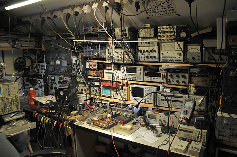
For the other forum regulars, here's a link to a picture on his web site of part of his shop:
Would you post back with a picture of the actual part once you have it built?
Also, interesting work you do. Thinking of pictures, I really like that picture of the gate between two trees in the show (now that the weather is nice here).
For the other forum regulars, here's a link to a picture on his web site of part of his shop:
Re: recognizing faults
Hi Bejant, that picture I made in the street I live. It is one of a serie I made that day. The snow was fresh and the light was marvouless. My side of the street was covered with fog but on the oposite side of the street the sky was blue. I took my car and made some very nice pictures.  this is in the same street but looking the other way.
I do not know if this is linkable but they can be found here: https://picasaweb.google.com/103257482059619681214/Temp
Today I printed most parts but 2 things went wrong. I somehow must have changed something because the top was compressed in width but extended in depth. But after cleaning up the design, the second one was good. I made a mistake with the knob too. I designed it using the diameter size for the radius datum. So it was twice the size,
The electronics are allready mounted and tested in the cabinet. It is a very simple but well performing 2X 10W amplifier, I had some doubts about the switching psu adapter I wanted to use, so I did some load tests and analysed the output of the psu under squarwave, stable constant and triangle loading. Selected a better and linair one from my junkbox. It is now complete silent with no input.
The cabinet came out better as I hoped. Not perfect but I like it. Very usable. This was my first serious 3D print. Tommorow I will print the knob. I made some photos and a blog page so if the knob is ready I will make a photo from the outside and publish it and place a picture here too, Without the help of the good people here I would have cost me a lot more time.
And I'm hooked on 3D cad now. I almost never draw pcb's. That is not my idea of fun. I wanted a 3D printer since the first time I heard about it but the fact I needed to use a cad program for it stopped me. But the more I play around with Freecad and use the technics I learn from the Freecad community, the more fun it gets. A whole new world of possibilities for homebrew.
This gave me a new idea. I make pcbs by plotting on the copper from a pcb with an edding marker in an old HP plotter. This works but the results are not constant due to the marker. I'm going to test if pla is resistant for the yellow stuff I use to remove the copper. If so will use the 3d printer to print a pcb layout.
this is in the same street but looking the other way. I do not know if this is linkable but they can be found here: https://picasaweb.google.com/103257482059619681214/Temp
Today I printed most parts but 2 things went wrong. I somehow must have changed something because the top was compressed in width but extended in depth. But after cleaning up the design, the second one was good. I made a mistake with the knob too. I designed it using the diameter size for the radius datum. So it was twice the size,
The electronics are allready mounted and tested in the cabinet. It is a very simple but well performing 2X 10W amplifier, I had some doubts about the switching psu adapter I wanted to use, so I did some load tests and analysed the output of the psu under squarwave, stable constant and triangle loading. Selected a better and linair one from my junkbox. It is now complete silent with no input.
The cabinet came out better as I hoped. Not perfect but I like it. Very usable. This was my first serious 3D print. Tommorow I will print the knob. I made some photos and a blog page so if the knob is ready I will make a photo from the outside and publish it and place a picture here too, Without the help of the good people here I would have cost me a lot more time.
And I'm hooked on 3D cad now. I almost never draw pcb's. That is not my idea of fun. I wanted a 3D printer since the first time I heard about it but the fact I needed to use a cad program for it stopped me. But the more I play around with Freecad and use the technics I learn from the Freecad community, the more fun it gets. A whole new world of possibilities for homebrew.
This gave me a new idea. I make pcbs by plotting on the copper from a pcb with an edding marker in an old HP plotter. This works but the results are not constant due to the marker. I'm going to test if pla is resistant for the yellow stuff I use to remove the copper. If so will use the 3d printer to print a pcb layout.