Hello guys,
I am new at Freecad and started with some sketches I want to extrude.
First sketch + pad worked ok.
But 2 issues arose then for the next sketches/pads:
- it does not allow to pick up external geometries that are in the same plane (hence the sketch 2 which uses only the point of reference) except if I make the sketch using the face containing the edges I want (sketch 4)
- once my second sketch is done, I cannot pad it properly (pad4). If I do so, for some reason the pad created is the first one (and I am sure of the sketch I selected).
Another thing, I tried extrude in the part workbench, and it allows me to extrude from the sketch that did not work with pad. However I cannot make a solid out of it (the part is hollow).
I spent a couple of hours around this issue, and cannot figure out what I do wrong.
any ideas?
Thanks
The refs:
OS: Ubuntu 13.10
Platform: 64-bit
Version: 0.13.1830 (Git)
Branch: releases/FreeCAD-0-13
Hash: ec7636d7aaf2612e9b43cff5d6a424037d53e505
Python version: 2.7.5+
Qt version: 4.8.4
Coin version: 4.0.0a
SoQt version: 1.5.0
OCC version: 6.5.4
Cannot make a pad out of sketch, issues with external geom
Forum rules
and Helpful information
and Helpful information
IMPORTANT: Please click here and read this first, before asking for help
Also, be nice to others! Read the FreeCAD code of conduct!
Also, be nice to others! Read the FreeCAD code of conduct!
Re: Cannot make a pad out of sketch, issues with external ge
Yes to use the tool to link to external geometry the sketch needs to be on the face of the feature (pad1). Sketch2 is separate sketch and you will not be able to use link to external geometry tool for pad1.- it does not allow to pick up external geometries that are in the same plane (hence the sketch 2 which uses only the point of reference) except if I make the sketch using the face containing the edges I want (sketch 4)
Yes the sketch would need to "touch" pad1 to create single part and not 2 independent ones:- once my second sketch is done, I cannot pad it properly (pad4). If I do so, for some reason the pad created is the first one (and I am sure of the sketch I selected).
viewtopic.php?f=3&t=6280
It looks like there are some issues with sketch4 but probably you only get hollow Extrude because the sketch is not closed.Another thing, I tried extrude in the part workbench, and it allows me to extrude from the sketch that did not work with pad. However I cannot make a solid out of it (the part is hollow).

Re: Cannot make a pad out of sketch, issues with external ge
Greetings picad,
Sketch003 from which you created Extrude has no constraints. Each endpoint should be constrained coincident to the endpoint of the adjacent segment. Also, delete "Extrude" by clicking on it in the tree view and selecting delete. After you've got the endpoints constrained coincident to one another, close the sketch but don't go to the Part workbench. Instead stay in the Part Design workbench and from the Tasks tab select Pad, then pad the 2500mm like you did before.
Sorry but I'll have to look into the other issues later.
Re: Cannot make a pad out of sketch, issues with external ge
One other thing, you would do yourself a big favor by upgrading your version of FreeCAD. I just noticed this post which will be of help to you.
Re: Cannot make a pad out of sketch, issues with external ge
OK, here we go:
The Part Design workbench is best suited for making a model of one item. It seems you're trying to model something like a foundation, maybe some piers, and maybe an interior wall. You can use the Part Design workbench for this, but if this is the approach you choose to take you would be better off to make separate models (files) for each of: spread footings, footing pads, foundation wall, framed interior wall, etc. You would have to locate each model precisely in the 3D space, and then use File -> Merge Project to bring them all together.
A much better approach would be to use the Arch workbench, and Yorik has tutorials on his blog. Now onto your post specifics:
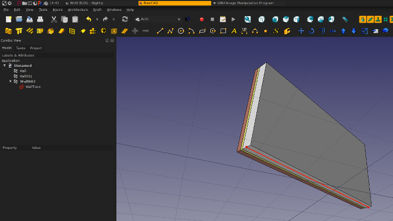
With your model open I would do File -> New, then click on Sketch4 to select it, then click on the new model tab at the bottom of the 3D window (it will be "Unnamed") then Edit -> Paste, select NO to the pop-up window about copying dependent objects. Now you have to constrain all the line segments coincident with the endpoints of the adjacent segments (there are 120 degrees of freedom - unconstrained things!). Now Pad from the Part Design workbench instead of Part WB -> Extrude to make your interior wall. The interior wall is a separate file which you will have to Merge into your final model.
That's all for now so feel free to post back if you need more help.
The Part Design workbench is best suited for making a model of one item. It seems you're trying to model something like a foundation, maybe some piers, and maybe an interior wall. You can use the Part Design workbench for this, but if this is the approach you choose to take you would be better off to make separate models (files) for each of: spread footings, footing pads, foundation wall, framed interior wall, etc. You would have to locate each model precisely in the 3D space, and then use File -> Merge Project to bring them all together.
A much better approach would be to use the Arch workbench, and Yorik has tutorials on his blog. Now onto your post specifics:
The issue is not that the external geometry is on the same plane; the issue is that the external geometry is on a different object. Using your approach you would be better off to model the footings under the foundation wall first, then Map a Sketch to the top, use Link to External Geometry Tool to link the location of the foundation inwards from the outer edges of the footing, and Pad up your 2500mm. Then select the top of the footing again, create a new Sketch for the interior (framed?) wall, use Link to External Geometry tool to link to either the inside of the foundation wall or maybe he inside of the footing. But when you Pad this Sketch, the footing, foundation wall, and interior wall will all be one homogenous thing. So, this may not be what you want.picad wrote:But 2 issues arose then for the next sketches/pads:
- it does not allow to pick up external geometries that are in the same plane (hence the sketch 2 which uses only the point of reference) except if I make the sketch using the face containing the edges I want (sketch 4)
That's the first time I've seen this, but Pad4 is dependent on Sketch4 which is dependent on Pad1. Sketch4 also has no constraints. Also, your model is forked; in the Part Design workbench it should be mostly linear.picad wrote:- once my second sketch is done, I cannot pad it properly (pad4). If I do so, for some reason the pad created is the first one (and I am sure of the sketch I selected).
- 20140409f_picad.jpg (30.2 KiB) Viewed 5470 times
That's all for now so feel free to post back if you need more help.
Re: Cannot make a pad out of sketch, issues with external ge
So many answers already!
First, sorry for the unconstrained sketch, I was trying to clean my project for the example, but in doing so I overlooked some basic requirements (well actually I probably deleted some references)... However, properly constrained the problem (or rather phenomenon) is exactly the same. I attached my "real" project (but nothing new in it compared to the demo).
Second I expected that external geometry would allow you to pick up any vertex or edge that is in the plane of the sketch. Actually I even expected that to be able to pick up any edge made by the intersection of surface with the sketch plane. Too much expectations (but Freecad looks so pro, it is easy to have high expectations).
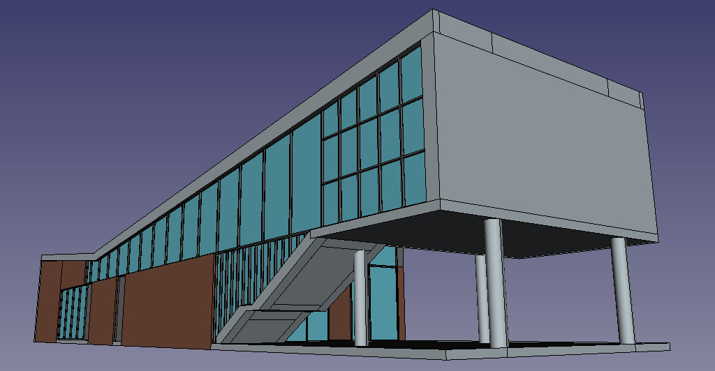
In fact I am trying to modelize a house of which I have a drawing. Since dimensions are not from a single reference point, it is way easier to draw using "external geometries". It also makes sense, since the insulation must follow walls for instance. That's why I did not try to do several independant parts.
But I definitly need to look at the Arch workbench (to my defense I was trying to evaluate the tool, and picked up the drawing I had in hand).
I did not know about the linear model 'requirement' in part design WB. Anyway the fork I have just comes from the fact that I copied pasted the sketch I was not able to pad, in order to extrude it. Which worked, except that it is not a solid.
Following your advice, I installed the latest development release.
Upon start up the extrusion seems in better shape, but getting in a sketch takes forever (well more accurately 31 seconds with one core working at 100%). I can reproduce the pad 4 phenomenon (which I named pad 4 in the attached file too).
In my file, pad4 should be exactly the same thing as extrude.
Interesting thing, when I copied pasted the sketch (from extrusion in order to later draw pad 4), it asked: "The selected objects have a dependency to unselected objects.
Do you want to copy them, too?" (I clicked yes)
And it copied the pad to which belongs the external geometries of my copied sketch (mur extérieurs -> mur extérieurs 001). I guess that's what I was seeing the previous release of freecad (a hidden copy of the external geometries pad).
Anyway, I guess I am not doing this drawing according to Freecad logic. As said by bejant I should set fundations and then walls and interior walls. But using walls as external references for insulation or other walls would still be an issue.
BTW, I guess it is not possible to use geometries from another part (interactivaly)?
Please do not think I complain, Freecad looks amazing and is free!
Hopefully I will be able to help this project someday. OS: Ubuntu 13.10
Platform: 64-bit
Version: 0.14.3402 (Git)
Branch: master
Hash: dc0bbee020a72a0ad1f868527c7af6a4cb06184e
Python version: 2.7.5+
Qt version: 4.8.4
Coin version: 4.0.0a
SoQt version: 1.5.0
OCC version: 6.7.0
First, sorry for the unconstrained sketch, I was trying to clean my project for the example, but in doing so I overlooked some basic requirements (well actually I probably deleted some references)... However, properly constrained the problem (or rather phenomenon) is exactly the same. I attached my "real" project (but nothing new in it compared to the demo).
Second I expected that external geometry would allow you to pick up any vertex or edge that is in the plane of the sketch. Actually I even expected that to be able to pick up any edge made by the intersection of surface with the sketch plane. Too much expectations (but Freecad looks so pro, it is easy to have high expectations).
In fact I am trying to modelize a house of which I have a drawing. Since dimensions are not from a single reference point, it is way easier to draw using "external geometries". It also makes sense, since the insulation must follow walls for instance. That's why I did not try to do several independant parts.
But I definitly need to look at the Arch workbench (to my defense I was trying to evaluate the tool, and picked up the drawing I had in hand).
I did not know about the linear model 'requirement' in part design WB. Anyway the fork I have just comes from the fact that I copied pasted the sketch I was not able to pad, in order to extrude it. Which worked, except that it is not a solid.
Following your advice, I installed the latest development release.
Upon start up the extrusion seems in better shape, but getting in a sketch takes forever (well more accurately 31 seconds with one core working at 100%). I can reproduce the pad 4 phenomenon (which I named pad 4 in the attached file too).
In my file, pad4 should be exactly the same thing as extrude.
Interesting thing, when I copied pasted the sketch (from extrusion in order to later draw pad 4), it asked: "The selected objects have a dependency to unselected objects.
Do you want to copy them, too?" (I clicked yes)
And it copied the pad to which belongs the external geometries of my copied sketch (mur extérieurs -> mur extérieurs 001). I guess that's what I was seeing the previous release of freecad (a hidden copy of the external geometries pad).
Anyway, I guess I am not doing this drawing according to Freecad logic. As said by bejant I should set fundations and then walls and interior walls. But using walls as external references for insulation or other walls would still be an issue.
BTW, I guess it is not possible to use geometries from another part (interactivaly)?
Please do not think I complain, Freecad looks amazing and is free!
Hopefully I will be able to help this project someday. OS: Ubuntu 13.10
Platform: 64-bit
Version: 0.14.3402 (Git)
Branch: master
Hash: dc0bbee020a72a0ad1f868527c7af6a4cb06184e
Python version: 2.7.5+
Qt version: 4.8.4
Coin version: 4.0.0a
SoQt version: 1.5.0
OCC version: 6.7.0
Re: Cannot make a pad out of sketch, issues with external ge
In this second example it works as expected. For quick test delete everything else except Sketch001003004003 and use Extrude tool on it and don't forget to check Create solid option. It will produce what you are after therefore something else is the cause in modelling tree for the result you are seeing.First, sorry for the unconstrained sketch, I was trying to clean my project for the example, but in doing so I overlooked some basic requirements (well actually I probably deleted some references)... However, properly constrained the problem (or rather phenomenon) is exactly the same. I attached my "real" project (but nothing new in it compared to the demo).
No it doesn't work like that. Sketch has to be created on a face of external geometry for the tool to work.Second I expected that external geometry would allow you to pick up any vertex or edge that is in the plane of the sketch.
You could for sure model entire house as single part or as group of manually positioned parts without relations in Part Workbench and Part Design Workbench but i do believe Arch Workbench is actually what you are after and Yorik (main developer behind it) made great tutorial for it a short while ago:In fact I am trying to modelize a house of which I have a drawing. Since dimensions are not from a single reference point, it is way easier to draw using "external geometries". It also makes sense, since the insulation must follow walls for instance. That's why I did not try to do several independant parts.
But I definitly need to look at the Arch workbench (to my defense I was trying to evaluate the tool, and picked up the drawing I had in hand).
http://www.freecadweb.org/wiki/index.ph ... h_tutorial
For example creating walls in Arch Workbench:

http://www.freecadweb.org/wiki/index.ph ... _the_walls
And creating multilayer walls in Arch Workbench:
viewtopic.php?f=9&t=4715
Re: Cannot make a pad out of sketch, issues with external ge
Yes indeed, the latest release seems to enable the extrusion to be a solid.In this second example it works as expected
It should perhaps be advertised on the documentation that the development release could be preferred to the stable release at this early stage. Although thinking about it, my freecad became very slow (freezing 30 sec each time I go in a sketch) with this release.
BTW, what is the difference between a pad and an extrusion? From the documentation, it seems pretty similar.
I am still a little puzzled as for why we should have sketches "overlaping" to be able to pad them properly, although I do not think this limitation would prevent to draw any real world part.
I will definitly try the arch workbench, looks great from your pictures...
Re: Cannot make a pad out of sketch, issues with external ge
Did you compile FreeCAD yourself?picad wrote:Although thinking about it, my freecad became very slow (freezing 30 sec each time I go in a sketch) with this release.
Then you should set the CMAKE_Build_Type to: Release
This makes a more optimized code, which is needed for good Sketcher perfomance.
Ulrich
Re: Cannot make a pad out of sketch, issues with external ge
No I did not, just installed as sugested in the post recommended by bejant:ulrich1a wrote:Did you compile FreeCAD yourself?picad wrote:Although thinking about it, my freecad became very slow (freezing 30 sec each time I go in a sketch) with this release.
Then you should set the CMAKE_Build_Type to: Release
This makes a more optimized code, which is needed for good Sketcher perfomance.
Ulrich
Do you think I should uninstall and compile? Sounds like some work if I want to keep up with updates.sudo apt-add-repository --remove ppa:freecad-maintainers/freecad-stable
sudo add-apt-repository ppa:freecad-maintainers/oce-release
sudo apt-add-repository ppa:freecad-maintainers/freecad-daily
sudo apt-get update
sudo apt-get upgrade
Edit: opening a sketch: 30sec and an extra 1.3 GB of memory used (but it drops it just after opening the sketch)
Last edited by picad on Fri Apr 11, 2014 8:02 pm, edited 1 time in total.