recognizing faults

Post here for help on using FreeCAD's graphical user interface (GUI).
Forum rules
and Helpful information
IMPORTANT: Please click here and read this first, before asking for help

Also, be nice to others! Read the FreeCAD code of conduct!
pa4tim
Posts: 17
Joined: Tue Apr 15, 2014 5:17 pm

Re: recognizing faults

Post by pa4tim »

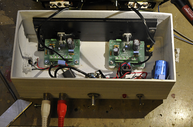
Here you find the whole story:
http://www.pa4tim.nl/?p=5038

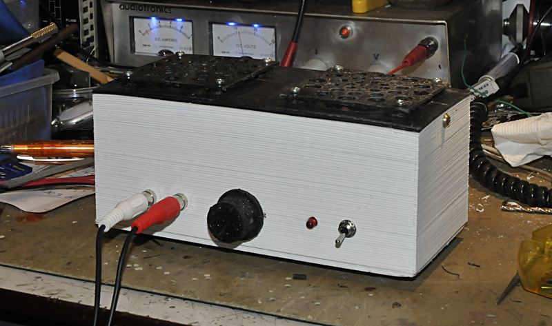
The pictures:
Image
Image

On to the next project. A boxinsert for a nice wooden cabinet o store my General radio connectors
User avatar
bejant
Veteran
Posts: 6075
Joined: Thu Jul 11, 2013 3:06 pm

Re: recognizing faults

Post by bejant »

Thanks for the nice writeup on your site. Below the image you have there of the Padded and Pocketed bottom piece I saw that you still needed the.stl format. To export your model from FreeCAD in .stl format, select the last, most recent Feature from the hirearchy tree. Don't select anything else too because the most recent Feature has all the previous model data, and doing so will produce a wrong .stl. Then File -> Export -> Save as type (bottom of the pop-up window) -> Mesh formats (.stl, etc). When you type the file name you need to also type the .stl extension too.

Just a minor thing, we call the FreeCAD modules "Workbenches" instead of "Workbanks".

And if you're interested, we've had a post in the forum from a fellow who used the free version of Eagle PCB to create his circuit boards into FreeCAD.
Some posts are here, here, and another thing is here.
pa4tim
Posts: 17
Joined: Tue Apr 15, 2014 5:17 pm

Re: recognizing faults

Post by pa4tim »

Thanks, I have changed it. Workbench is werkbank in Dutch so I mixed two languages. I think made the STL file like you discribed. The pictures on my side are made after I printed the cabinet and I played around a bit to get a nice picture. I go to the mesh workbench. Select the last file from the application tree (is that the hirearchy tree ? ) . Then create a mesh from plane. Then I use the analyse tools. If ready I select the mesh in the tree and export mesh and select stl from the filetypes.

About copy things like I asked, Iwas playing around with functions and benches and in the part workbench there is a copy function. Part from the menu and then select -create simple copy. I tried it on a sketch, a face and a solid and it worked perfect for all. It looks like is does not do anything but if you go to the data tab and alter the placement you see the copy moving out of the original.

The Eagle thing is (I think) a "plugin" like thing to make a 3D picture of the pcb + components. There is an open source electronic cad program that can do the same thing. if I remember well It is Kicad. I rather would use kicad, the max size of pcbs is much to small in Eagle (freeware version) but I'm used to eagle and I did not get Kicad to work like I wanted and missed the libs. (and I do not realy need it, most things I build manhattan or dead bug style.

Eagle has a CAM processor function. That lets you export a HPGL file. That was the main reason to use Eagle for me. My idea was draw a schematic in freecad and then print it. (I often do not need te components, autoroute etc. Or even better to find a tool that converts HPGL to Gcode. (pen up wil be Z up and X, Y stay the same)
Post Reply