Introduction and Bearing Creator Tool

Here's the place for discussion related to coding in FreeCAD, C++ or Python. Design, interfaces and structures.
Forum rules
Be nice to others! Respect the FreeCAD code of conduct!
javiermg
Posts: 7
Joined: Mon Aug 12, 2013 11:04 am

Re: Introduction and Bearing Creator Tool

Post by javiermg »

I have realized that some of my changes are the same that jreinhardt did, so I am going to work in that direction. I also found an online document that has very useful information about bearings, and tables with standard (I think so) sizes: http://www.neita.nl/lagers/koyocat203e.pdf

Finally, this is a script that creates caseless needle bearings, like this one:

Image

In a shaft with a bit of color:

Image

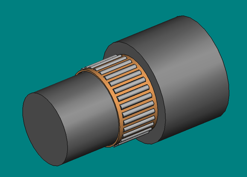
The function is called NB(outer radius, inner radius, width)

Code:

Code: Select all

import Part
import math
def NB(rout,rin,bth):
    rnd=(rout-rin)/2.00
    cnd=((rout-rin)/2)+rin
    nnd=2*math.pi*cnd/(1.8*2*rnd) #Needle number
    nnd=math.floor(nnd)
    nnd=int(nnd)   
    #needle cage--------------
    ncrout=cnd+0.175*(rout-rin)
    ncrin=cnd-0.175*(rout-rin)
    nc1=Part.makeCylinder(ncrout,bth)
    nc2=Part.makeCylinder(ncrin,bth)
    nc=nc1.cut(nc2)
    #needle space on the cage-
    rsnd=rnd*1.2
    thsnd=bth*0.8
    for i in range(nnd):
      snd=Part.makeCylinder(rsnd,thsnd)
      Alpha=(i*2*math.pi)/nnd
      nv=(cnd*math.cos(Alpha),cnd*math.sin(Alpha),0.1*bth)
      snd.translate(nv)
      nc=nc.cut(snd)      
    #Needle creation----------
    for i in range(nnd):
      nd=Part.makeCylinder(rnd,thsnd)
      Alpha=(i*2*math.pi)/nnd
      nv=(cnd*math.cos(Alpha),cnd*math.sin(Alpha),0.1*bth)
      nd.translate(nv)
      Part.show(nd)
    Part.show(nc)
    Gui.SendMsgToActiveView("ViewFit")
Next thing I want to do is searching about how to change the material to give it a better look, and possibly merge all bearing creators in the same script creating a more complex function.
jreinhardt
Posts: 329
Joined: Mon Sep 09, 2013 6:08 pm

Re: Introduction and Bearing Creator Tool

Post by jreinhardt »

Hi,

I incorporated both of these functions into BOLTS, using dimension data from http://medias.schaeffler.de/medias/de!hp/ (The SKF page suggested by mario was less convenient to copy-paste the hundreds of rows). This worked as planned, but the current graphical interface is not very well suited to choose from the 300 different kinds of needle bearings that it now knows about. (And now it is perfectly clear to me why Javier wants to have a search feature). So I will have to think about that.

Greetings

Johannes
BOLTS, standard parts library for FreeCAD Thread, Help with Translation
javiermg
Posts: 7
Joined: Mon Aug 12, 2013 11:04 am

Re: Introduction and Bearing Creator Tool

Post by javiermg »

Hi all.

I want to ask two things which are slowing down my work. I have not found them anywhere (nothing that I am able to understand, at least)

First, I am working at more complex bearings which need from creating sketches. I have managed to arrange lines and create a wire object easily, but now I need to revolve it in order to cut a solid, and I am facing a wall.
This is the wire I am trying to revolve and convert into a solid (to cut "our" with it)

Code: Select all

import Part
import math
from FreeCAD import Base

rout=100
rin=50
bth=50
RR=1
cbr=0.25*bth

#outer rin-----------
our1=Part.makeCylinder(rout,bth)
our2=Part.makeCylinder(rin,bth)
our=our1.cut(our2)
oure=our.Edges
our.makeFillet(RR,oure)
#Points:
bt2=bth/2.00
roin=rout-rin
A=Base.Vector(rout+0.1*rout, 0, bt2+bt2*0.15)
B=Base.Vector(rout-roin*0.2, 0, bt2+bt2*0.15)
C=Base.Vector(rout-roin*0.2, 0, bt2+cbr)
D=Base.Vector(rin+roin*0.2, 0, bt2+bt2*0.15)
E=Base.Vector(rin-0.1*rin, 0, bt2+bt2*0.15)
F=Base.Vector(rin-0.1*rin, 0, bt2-bt2*0.15)
G=Base.Vector(rin+roin*0.2, 0, bt2-bt2*0.15)
H=Base.Vector(rout-roin*0.2, 0, bt2-cbr)
I=Base.Vector(rout-roin*0.2, 0, bt2-bt2*0.15)
J=Base.Vector(rout+0.1*rout, 0, bt2-bt2*0.15)
#Lines
LA=Part.Line(A,B)
LB=Part.Line(B,C)
LC=Part.Line(C,D)
LD=Part.Line(D,E)
LE=Part.Line(E,F)
LF=Part.Line(F,G)
LG=Part.Line(G,H)
LH=Part.Line(H,I)
LI=Part.Line(I,J)
LJ=Part.Line(J,A)
CV=Part.Shape([LA,LB,LC,LD,LE,LF,LG,LH,LI,LJ])
CV=Part.Wire(CV.Edges)
RV=(0,0,1)
CV.revolve(RV,360)
Part.show(CV)
The command "CV.revolve(RV,360)" only gives errors and errors not matter what I try or in which order. Also I have not found any documentation of it.
Anyone knows how to revolve a wire and cut it to a solid? Is just impossible?


The second question is less important, but will complete the bearing script:

Is there any way to modify by command the color/material of a shape?


Thank you!! :)
Post Reply