It is best to quote only the part of a post you are directly referring to, that makes it easier to read. If people want to see the whole quoted post they can use the small uparrow link near the quoted name.
CNC Lathe and 4th-axis milling...
Forum rules
Be nice to others! Respect the FreeCAD code of conduct!
Be nice to others! Respect the FreeCAD code of conduct!
Re: CNC Lathe and 4th-axis milling...
A Sketcher Lecture with in-depth information is available in English, auf Deutsch, en français, en español.
Re: CNC Lathe and 4th-axis milling...
I haven't really looked much at 4th axis, and limited 3rd axis, lately.
Most recently, I've looked at using the getUVNodes() function for each face.
getUVNodes() returns a list of the UV values for the Face.
Parsing the list, the valueAt(u,v), and normalAt(u,v) return the vertex, and the normal at that UVNode.
If the normal.z isn't negative, the point can be milled from the +Z axis.
For example, if the tool is a square endmill, the tool tip response to that point is calculated by zeroing the normal.z, normalizing, and multiplying the vector by the tool radius and adding to the vertex point. Any tool shape can be similarly calculated, as radial and axial offsets, relative to the surface point.
I have not yet figured out how yet, but I believe it's possible to create a surface from the result tool points.
Here are pictures of toroid,
cone,
sphere results.
For these, I'm selecting a Job and Tool-Controller, and running script.
Most recently, I've looked at using the getUVNodes() function for each face.
getUVNodes() returns a list of the UV values for the Face.
Parsing the list, the valueAt(u,v), and normalAt(u,v) return the vertex, and the normal at that UVNode.
If the normal.z isn't negative, the point can be milled from the +Z axis.
For example, if the tool is a square endmill, the tool tip response to that point is calculated by zeroing the normal.z, normalizing, and multiplying the vector by the tool radius and adding to the vertex point. Any tool shape can be similarly calculated, as radial and axial offsets, relative to the surface point.
I have not yet figured out how yet, but I believe it's possible to create a surface from the result tool points.
Here are pictures of toroid,
- Toroid_000.png (201.39 KiB) Viewed 2146 times
- Toroid_001.png (205.58 KiB) Viewed 2146 times
- Cone_000.png (180.56 KiB) Viewed 2146 times
- Sphere_000.png (223.96 KiB) Viewed 2146 times
- Attachments
-
 Top3dMilling.FCMACRO
- (36.42 KiB) Downloaded 94 times
Re: CNC Lathe and 4th-axis milling...
Afternoon fellow FC enthusiasts and late night millers...
First, let me send many thanks to
Anyhow, I have not had a chance to complete this forum thread, word for word. I began, but have not time today to finish. I am liking the discussion very much and finding it quite useful.
JoshM's original, lengthy, post includes many necessary topics. I think perhaps, as for work flow in the PathWB, from a novice user of both FC and CNC machines is to include the option to rotate the work around the A (4th) axis at 90 degree intervals to allow access to each surface plane in the XY and XZ orientations. I think this would be a simple tool feature addition for 4th axis users to allow access to their work piece with existing PathWB tools. Just my two cents based on JoshM's commentary and my interaction with FC.
Back to the main idea for this thread, I see that JoshM and Sliptonic have shared a 4th axis script and related test models here on the forum. I too have had some collaboration with Sliptonic and would like to offer my scripting progress in this area to the FC community for input and collaboration. I used the 3D Surface tool in PathWB as the basis for my 4th axis adaptations. The new 3D Surface script has major modifications to Sliptonic's original work. I do think the new 4th axis operations should be separated from the original planear 3D Surface tool, and converted to a separate, stand-alone tool.
I have more commentary, but due to time constraints today, I'll have to continue later. I just would like to make the script available to you all. I have a FC fork on GitHub at https://github.com/Russ4262/FreeCAD. To use the modified PathSurface.py script, go to your FreeCAD/Mod/Path/Path Scripts folder. Rename your current PathSurface.py script to save it. Paste the attached script, or updated versions on my GitHub fork. Rename the pasted script to PathSurface.py. Restart FreeCAD and test away.
I have multi-pass(layering or StepDown) support included for most of the new operations, but not all.
Enjoy. Thanks in advance for the feedback. I am attaching the script and some screenshots of results.
Russ4262
First, let me send many thanks to
,JoshM wrote:@JoshM
andsliptonic wrote:@Sliptonic
for their assistance within and without the FC forums. It is much appreciated. And, these discussions are so much more worthwhile to me than that Harry Potter series... Which I have not read. Lol.herbk wrote:@HerbK
Anyhow, I have not had a chance to complete this forum thread, word for word. I began, but have not time today to finish. I am liking the discussion very much and finding it quite useful.
JoshM's original, lengthy, post includes many necessary topics. I think perhaps, as for work flow in the PathWB, from a novice user of both FC and CNC machines is to include the option to rotate the work around the A (4th) axis at 90 degree intervals to allow access to each surface plane in the XY and XZ orientations. I think this would be a simple tool feature addition for 4th axis users to allow access to their work piece with existing PathWB tools. Just my two cents based on JoshM's commentary and my interaction with FC.
Back to the main idea for this thread, I see that JoshM and Sliptonic have shared a 4th axis script and related test models here on the forum. I too have had some collaboration with Sliptonic and would like to offer my scripting progress in this area to the FC community for input and collaboration. I used the 3D Surface tool in PathWB as the basis for my 4th axis adaptations. The new 3D Surface script has major modifications to Sliptonic's original work. I do think the new 4th axis operations should be separated from the original planear 3D Surface tool, and converted to a separate, stand-alone tool.
I have more commentary, but due to time constraints today, I'll have to continue later. I just would like to make the script available to you all. I have a FC fork on GitHub at https://github.com/Russ4262/FreeCAD. To use the modified PathSurface.py script, go to your FreeCAD/Mod/Path/Path Scripts folder. Rename your current PathSurface.py script to save it. Paste the attached script, or updated versions on my GitHub fork. Rename the pasted script to PathSurface.py. Restart FreeCAD and test away.
I have multi-pass(layering or StepDown) support included for most of the new operations, but not all.
Enjoy. Thanks in advance for the feedback. I am attaching the script and some screenshots of results.
Russ4262
- Attachments
-
- Example_Lathe_Eyelet - 4th axis - perpendicular(circular).png (433.19 KiB) Viewed 1991 times
-
- PathSurface_r3g-usable.py
- PathSurface script
- (62.26 KiB) Downloaded 48 times
-
- Example - X-axis rotational - single-pass - gcode path improved.pdf
- (173.38 KiB) Downloaded 77 times
-
- Example - X-axis rotational - perpendicular - single-pass.pdf
- (253.89 KiB) Downloaded 53 times
-
- Example_Lathe_Eyelet - 4th axis.png (432.08 KiB) Viewed 1991 times
Re: CNC Lathe and 4th-axis milling...
Hi Russ,
Great work--really appreciate what you're up to! I'm trying to take a look at your script now. I haven't gotten 4th axis, but I'm amazed at what's been done so far with harnessing OCL to fit into PathWB better. If I recall correctly, AWallin had built in various tool-tip types--end, ball, chamfer, etc..., but I don't think that aspect of OCL was ever linked in the PathWB 3dSurface OP. Is that something you have done or are planning to do?
Best,
Josh
Re: CNC Lathe and 4th-axis milling...
Evening, Josh.
I have thought about your question:
Actually, Sliptonic included code in the 3D Surface Op that sends tool details from the tool controller to OCL. At the moment, I only see support for the end mill and ball nose cutters in the existing code. Looking at AWallin's source code or documentation, https://github.com/aewallin/opencamlib, for additional insight to cutter shapes supported in his openCamLib, I see a ball, a bullnose, a composite, a cone(chamfer?), an ellipse, and a cylindrical cutter listed. Adding additional support in the FC op is something I will look into as I continue working on the 3D Surface Op and related 4th axis op implementations. My current thought is that Sliptonic understands the needs for expanding cutter integration with the current 3D Surface op.
Relating to the modified 3D Surface Op I shared for collaboration, I understand it is only a starting point for some of the ideas shared in this thread. I suppose it is an second proof of concept in addition to the macro you and Sliptonic collaborated on. A few thoughts:
Thanks,
Russell
I have thought about your question:
.
Actually, Sliptonic included code in the 3D Surface Op that sends tool details from the tool controller to OCL. At the moment, I only see support for the end mill and ball nose cutters in the existing code. Looking at AWallin's source code or documentation, https://github.com/aewallin/opencamlib, for additional insight to cutter shapes supported in his openCamLib, I see a ball, a bullnose, a composite, a cone(chamfer?), an ellipse, and a cylindrical cutter listed. Adding additional support in the FC op is something I will look into as I continue working on the 3D Surface Op and related 4th axis op implementations. My current thought is that Sliptonic understands the needs for expanding cutter integration with the current 3D Surface op.
Relating to the modified 3D Surface Op I shared for collaboration, I understand it is only a starting point for some of the ideas shared in this thread. I suppose it is an second proof of concept in addition to the macro you and Sliptonic collaborated on. A few thoughts:
- I chose to modify the existing 3D Surface script rather than a macro for no particular reason, other than I opened the script and began to work with what was there. I am still not very familiar with the QT UI structure and, well, it still seems foreign, but not without comprehension.
- The nomenclature used for the added property inputs needs improvement for standardization in the field. I need to reference some of the milling/lathe sites you have mentioned in this thread.
- We should add rotational degree min and max inputs to allow more control.
- I suspect the existing 3D Surface op has a bug related to the SampleInterval.
- For rotational scans, the Drop Cutter Direction currently serves as the axis of rotation selection. This needs to be moved to a separate property input.
- When Scan Type is set to rotational, the work flow is: Determine the radius of the required stock. Determine the circumference. Use the StepOver value applied at circumference to determine the number of angular indexes. A straight line scan parallel to the axis of rotation is made on the model using OCL. The model is rotated to the next index, scanned, and the process continues. The OCL scan data is then processed to gcode. This process is used whether the Cutter Travel Orientation is parallel or perpendicular; if perpendicular, the scan data is re-grouped into circular rings at SampleInterval points - which are equal in number for each linear scan at each index.
- In the modified version, the roles of SampleInterval and StepOver values are reversed when Cutter Travel Orientation is set to perpendicular. Consequently, they do not allow for proper input from the user.
- I would like to add layering support for the perpendicular rotational scans. I just haven't had the time to make the implementation.
- The modified script has a few bugs. One specific bug has to do with successive iterations of the operation. My FC crashes sometimes if I run the operation, get the result, then change for example the Drop Cutter Direction, then re-compute the operation. I don't know if it is a Qt UI backend issue, a PathWB issue, or what. I wonder if the size of the gcode output from the operation has any bearing on the crash issue.
- The Cut Mode property, like that of the 3D Pocket tool, needs to be added and implemented.
- A scan angle property similar to the Pattern property of the 3D Pocket tool could be implemented such that the scan lines can be set to any desired angle, not just set to axis of rotation. At first thought, this would not be too difficult to code as proof of concept.
- We need to separate the 4th axis operation from the original planear 3D Surface op (leaving the layering support for the planear op)
Thanks,
Russell
-
sliptonic

- Veteran
- Posts: 3460
- Joined: Tue Oct 25, 2011 10:46 pm
- Location: Columbia, Missouri
- Contact:
Re: CNC Lathe and 4th-axis milling...
I'd hacked up a similar implementation of the dropcutter to 4th axis operation.
A simple test shape
Set up the job and generate the path
Chuck up some foam in a 4th axis. (This attempt failed when my foam came apart. I tried again with slightly modified setup)
Success
Russ, You're right about the toolshapes in OCL. We need to do some work on the tool library and TC to support the additional attributes needed for the other OCL tool types.
I think your implementation is farther along than mine. It looks like you've got zigzagging working. I'm only going unidirectional so far. Mine is in a completely separate operation though. My branch is here: https://github.com/sliptonic/FreeCAD/tr ... e/4thcarve
I'd suggest that we NOT do a pull request to FreeCAD master yet. Nothing is going to get merged until after 0.18 is released anyway and this deserves more testers before we merge anything.
I think you should definitely split the 4th axis and the regular surface stepdown code into two branches. If you want, you can take off from my branch and modify the 4thCarve operation with your implementation. I can help with the UI stuff as well. We can do integration in my branch and do a PR from there when it's ready.
I played with your a bit this morning and can't get stepover to behave the way I want. I would expect that if stepover is 100%, the parallel tool path lines on a given stepdown level would be 1 tool diameter apart. Maybe I'm running into what you described above.
This is looking very cool!
A simple test shape
- p1.png (13.72 KiB) Viewed 1849 times
- p2.png (258.82 KiB) Viewed 1849 times
- p3.jpg (133.66 KiB) Viewed 1849 times
- p4.jpg (117.67 KiB) Viewed 1849 times
I think your implementation is farther along than mine. It looks like you've got zigzagging working. I'm only going unidirectional so far. Mine is in a completely separate operation though. My branch is here: https://github.com/sliptonic/FreeCAD/tr ... e/4thcarve
I'd suggest that we NOT do a pull request to FreeCAD master yet. Nothing is going to get merged until after 0.18 is released anyway and this deserves more testers before we merge anything.
I think you should definitely split the 4th axis and the regular surface stepdown code into two branches. If you want, you can take off from my branch and modify the 4thCarve operation with your implementation. I can help with the UI stuff as well. We can do integration in my branch and do a PR from there when it's ready.
I played with your a bit this morning and can't get stepover to behave the way I want. I would expect that if stepover is 100%, the parallel tool path lines on a given stepdown level would be 1 tool diameter apart. Maybe I'm running into what you described above.
This is looking very cool!

Re: CNC Lathe and 4th-axis milling...
Great success!
Please do not forget about more simple manual operations setup. I did some tilting platform tests with simple kinematics, the only difference from 360 degree rotary is that on the platform the 0 point is shifted away from rotation axis, kinematics corrects this and I can use code generated in Freecad from models rotated around their 0 point (I use the middle of the bottom face). This works for me now, I create clones and rotate them and then use their faces for code. I'm not sure how to do it better, as having more and more models is awkward. The way I output the rotation in the postprocessor is even more awkward... Not very bad for 3 faces but this does not scale well. I tried to dig in the code but it is getting more and more complicated and it needs a good approach, that will respect the shape of stock too and will not need clones, or not manual ones that pop all together when I click new operation. For rotated cylinder it does not change much, but rotated flat box can waste a lot of time milling air when processed with ordinary zmax. After much manual optimization it works well enough. I can link the pocket depth to start depth of drilling and that works when I change the pocket angle. With manual eccentric brake the rotary is much stiffer. Next upgrade is the air actuator...
Here is one earlier attempt: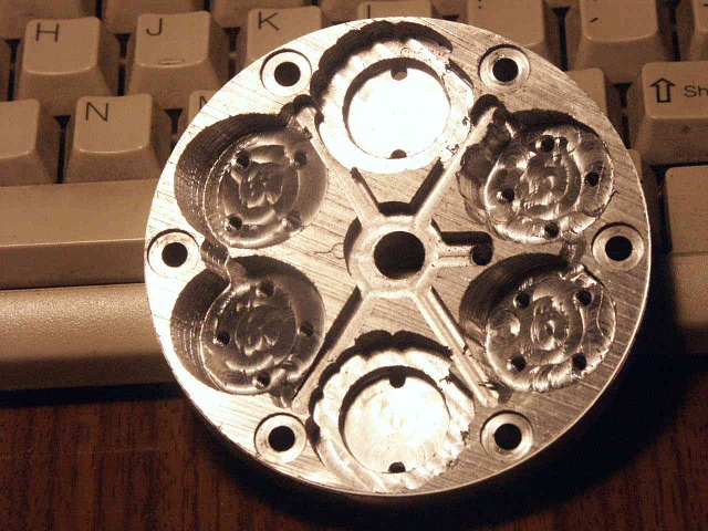
I need to start playing with Your code and look around, maybe its there already
Is it already possible to limit the calculated rotation to 180 deg to mill like a half-sphere?
Thanks!
Re: CNC Lathe and 4th-axis milling...
I have begun isolating this linkage between OCL and the FC tool controller. I am using Sliptonic's code snippets in the 3D Surface Op as a starting point.
Due to my lack of knowledge and expertise in this area of CNC milling and lathe processes, I am reaching out to you. I noticed that the existing FC tool controller[TC] has some fields for some tools that are extraneous to the tool, as I understand the tools. I have been looking for images and diagrams online to teach myself about the technical terms and characteristics of the available tools in FC and those available in OCL; I could use some pointers to quality resources, please. The FC TC parameters do not all coincide with those arguments passed to OCL functions. So, I need some help with visuals related to the current tool selection and parameters in the FC TC so I can map them, or calculate correct values, for passing to OCL.
I do intend to reach out to AWallin and request some clarification on some of the cutters, and their necessary function arguments, he has available that are not as straight forward to me at this time. I figure if I have some diagrams labeled to use as reference that would encourage his assistance.
Thanks,
Russ
I have installed GitHub Desktop, and copied both the FreeCAD and AWallin's OpenCamLib repositories to my local terminal.
Due to my lack of knowledge and expertise in this area of CNC milling and lathe processes, I am reaching out to you. I noticed that the existing FC tool controller[TC] has some fields for some tools that are extraneous to the tool, as I understand the tools. I have been looking for images and diagrams online to teach myself about the technical terms and characteristics of the available tools in FC and those available in OCL; I could use some pointers to quality resources, please. The FC TC parameters do not all coincide with those arguments passed to OCL functions. So, I need some help with visuals related to the current tool selection and parameters in the FC TC so I can map them, or calculate correct values, for passing to OCL.
I do intend to reach out to AWallin and request some clarification on some of the cutters, and their necessary function arguments, he has available that are not as straight forward to me at this time. I figure if I have some diagrams labeled to use as reference that would encourage his assistance.
Thanks,
Russ
Re: CNC Lathe and 4th-axis milling...
May I also suggest we separate the OCL Waterline from the regular surface op since it seems unused at this time. I'd like to take a look at it in the future. I can see it being an independent tool on the PathWB.sliptonic wrote: ↑Mon Mar 11, 2019 6:52 pm I think you should definitely split the 4th axis and the regular surface stepdown code into two branches. If you want, you can take off from my branch and modify the 4thCarve operation with your implementation. I can help with the UI stuff as well. We can do integration in my branch and do a PR from there when it's ready.
Also, will you please email me the FC model file you used above in this post for your rotational foam test run.
Thanks,
Russ
-
sliptonic
- Veteran
- Posts: 3460
- Joined: Tue Oct 25, 2011 10:46 pm
- Location: Columbia, Missouri
- Contact:
Re: CNC Lathe and 4th-axis milling...
I don't know if it needs to be a separate operation. Maybe. But I'm o.k. with removing it from active use at this time. Awallin stated somewhere that the waterline algo in OCL needs serious work so I don't think we can make it useful from our side.