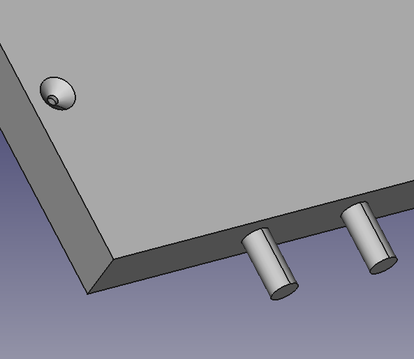
You a re referring to this?
dprojects wrote: ↑Mon Jan 17, 2022 10:22 am
In our time dimension, I mean FreeCAD, You can't add custom description (custom text) for object. You can do it in python, add custom property to existing object, but there is no GUI for that at FreeCAD during designing furniture.
Also You can't add custom text to the edge except "constrain name".
A Face or an edge is a "building component" of a Solid, not an object with a proper "life".
This is not a thing you could change from the actual way, is a completely different way of thinking things, as a solid is defined as a unique object not a "sum of components".
You could store some components as separate objects, and maybe name them, if they share same placement, they are shown in same place.
You could add some arrow that points to a position, and name them.
But I doubt that a CAD will permit you to name a "building component".
Maybe there is some "basic comprehension" that lacks about modelling.
See under Topology what are Faces, Edges in respect to a Solid.
https://wiki.freecadweb.org/Topological_data_scripting
When you model, you could make a wire, then make a face using the wire, then extrude the face to make a solid, and retain all the intermediate objects, simply use copy of them.
You have three objects, so you must have a way to quickly switch between the "whole view" and the detail view, for this you could use Layers.
You have two layers, "Solids" and "Components", maybe more than one, each one will show what you need and could have a proper Name (or better Label shown in the combo view)
But this is a design choice, you could make a macro or a whole program to model things, and make it behave in whatever manner you want. it is simple matter of time and work.
I have done similar work and users are satisfied with the way of work, at the end of the program run only the "final solid" is shown, but there are Layers that could be activated to show the "building components", in my case, wires or subcomponents, I have done some work to carve fretboards, using a semicircular carve following the curved profile of fretboard, and the final solids are "frets holes" as they are the solid passed to the CNC program to carve.
Buy selecting a Layer named "Fretboard" user could show the fretboard itself and selecting another Layer named "Construction" it could show "building dimensions" like fretboard curvature, fretboard length and arrows naming each solid as "fret n 1" and so on, each fret has a proper "Label" (Name property for some solids is assigned by FreeCAD so you could alter only Label that is shown in comboview).
As said Draft layers could divide the view and make it less crowded, and maintain an high level of flexibility, you could set a property to Hide or Shown them so what is shown at the end of the "generating program run" is a design choice.
Regards
Carlo D.