How would one integrate rain gutters using BIM ?
For example, extruding them across a roof siding...testing different configurations ?
Gutter Info
Proper Pitch
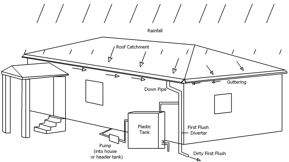
Gutter installation should follow a couple basic rules. Gutters must be pitched so water will flow to the downspouts. The rule of thumb for this slope is a vertical 1/2 inch for every 10 feet of horizontal run. If the run is more than 35 feet long, some specialists recommend installing the high point of the system in the middle and sloping the gutter downward in both directions to downspouts on both ends of the run. Water exiting the downspout must always be directed away from the foundation.
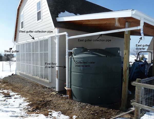
I was thinking it would be cool to auto-generate gutters the way @paullee is autogenerating staircases. The gutters can be configured differently depending on the utility. For example, if someone was interested in rainwater harvesting etc...
The thing is, designing gutters and water collection systems is a complex thing. Hard to automate, there are many models and systems out there...
Basically it's almost the same problem as hydraulics system and HVAC (air conditioning) design: It's all a matter of pipes and devices.
- pipes (which can be a LOT of things: normal, rounded pipes, large square pipes (air conditioning), half-open pipes (gutters), etc. They need to follow a line and they need to connect with other things (other pieces of pipes and devices)
- devices are objects that are placed along a "route" of pipes, like corner pieces or faucets or ventilators or air dispensers
The basis for these exists in Arch WB already: pipes and connectors. Other kinds of devices ATM could be imported from step files or so, but there is lack of proper tools to place them easily or automatically on a route or pipes...
Hopefully some engineer may provide a ? mathematical model ? representing the pipeworks that could be used. I am far from understanding the engineering aspects + not having coding / python knowledge enough.
Arch Pipe and Draft Slope currently helps to construct the model, I guess Flamingo also help.
Maybe the slope can be set 'automatically' (like tread / riser) .... but I once thought there should be 'input' and 'output' so at the end of a pipeworks (or ductworks) system, there should be 'total' of say discharge volume etc.
Maybe any engineer want to implement more feature on top of Draft Slope / ArchPipe / Arch Connector ?
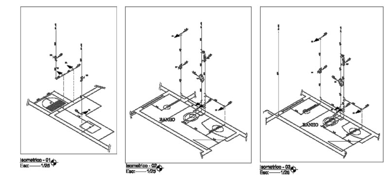
What I see around is that most people who work with tube networks basically work with linear diagrams: You draw lines (or curves, or polylines, ...) that represent your wires/tubes. In many cases, the drawings you print actually show these lines, not the 3D tube, ex:
If we have such a linear diagram, indeed adding the tubes is easy (Arch Pipe or Flamingo/Dodo Pipe)
Another improvement we could add to those pipes is the possibility to display a text label at the center...
Indeed engineer do not start drawing 3d, that's not helpful at start.
Plan and vertical diagrams serve their schematic design study requirements.
I was thinking, if and how, a 3d lines could be 'projected' on 2d planes to provide the same vertical diagram - in this Mode the horizontal position does not matter too much - this diagram should allow users to move the 'represented horizontal positiom' to say illustrate grouping of fitting.
Too complicated ? I would spend more time understand how Arch/BIM works and see any small tasks can be done myself ATM
yorik wrote: ↑Tue Jul 16, 2019 2:35 pm
but there is lack of proper tools to place them easily or automatically on a route or pipes...
paullee wrote: ↑Tue Jul 16, 2019 4:34 pm
Maybe the slope can be set 'automatically' (like tread / riser) .... but I once thought there should be 'input' and 'output' so at the end of a pipeworks (or ductworks) system, there should be 'total' of say discharge volume etc. Maybe any engineer want to implement more feature on top of Draft Slope / ArchPipe / Arch Connector ?
yorik wrote: ↑Wed Jul 17, 2019 2:45 pm
Another improvement we could add to those pipes is the possibility to display a text label at the center...
Could we consider opening tickets to address these issues ?
Maybe some MEP / E&M / Building Services Engineer provide some comments.
Basically, drawing some draft wire and turn it into pipe-like object seems was something done by @Yorik @Oddtopus. @bitacovir suggested attaching the wire / pipe to a wall in other thread - should be doable ...
But it is about BIM, information maybe like which end of wire / pipe is the inlet and which is outlet.... input of discharge / incoming at ends of branches, and then the other end of main pipe should have 'outcome' / summation value... need an engineer to advise