
Hi,
i tried to import DXF files from a script. They are all 2D. In need to convert the contents of a single layer to a planar surface, so i can extrude or revolve it.
In openSCAD example 007 there a tree layers. In two of them there are seperate lines but they form a closed wire. In the layer 'dorn' the lines can be joined to an open wire and afterwars be closed. I took some code from the Upgrade function from the Draft module to do that.
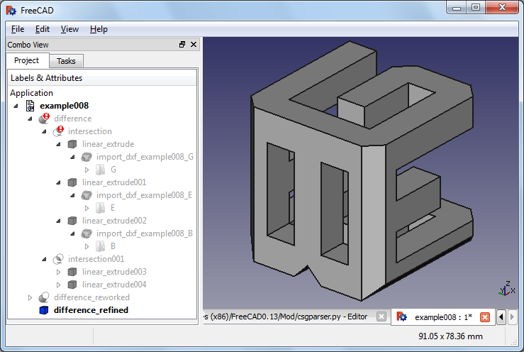
In OpenSCAD example 008 there are four layers. All of the line segments for closed wires. But in layer 'B', there are tree closed wires assembling the letter 'B'.
I need way to detect the closed wires from a unordered list of edeges. And i need a way to tell wich face is outer and which faces are inner to i can do a boolean subtraction (as a boolean xor) is not available.
Does anyone know algorithms that can acomplish the above?
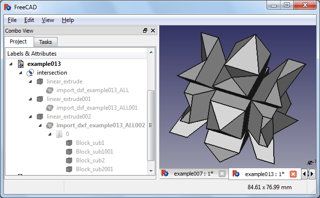
In OpenSCAD example 013 the dxf import returns me blocksubs. The breaking up in the edges gives back a face. But the applied extrusions and intersection take up several minutes and create a odd shape.
Is there a way to handle these blocksubs wich are in this examples open wires that can be joined to a closed wire.
Version: 0.13.0687 win7
processing imported DXF
Forum rules
and Helpful information
and Helpful information
IMPORTANT: Please click here and read this first, before asking for help
Also, be nice to others! Read the FreeCAD code of conduct!
Also, be nice to others! Read the FreeCAD code of conduct!

Re: processing imported DXF
Hm no, I think you'll need to make up something yourself... Have a look in Draft fcgeo.py, there are 2 function that you could use and adapt: sortEdges, which takes a list of edges and sorts (and reverses if needed), it is an "upgraded" version of the standard Part.__sortEdges__, and superWire, which forces a closed wire out of a list of edges, even if slightly disconnected. Note that OCC also has a way to force wires out of disconnected edges.
-
keithsloan52
- Veteran
- Posts: 2764
- Joined: Mon Feb 27, 2012 5:31 pm
Re: processing imported DXF
Would a Kludge be to import the DXF file into FreeCAD and then export as a Mesh. Then load the Mesh file rather than the DXF file.
-
keithsloan52
- Veteran
- Posts: 2764
- Joined: Mon Feb 27, 2012 5:31 pm
Re: processing imported DXF
Okay if importers support import as well as open. Could one not just import a DXF file, then somehow select it all then extrude. I am able to do this via the GUI, can it be done programatically.
Re: processing imported DXF
If you can describe what you did this can be a good starting point. One problem here is that the 'Upgrade/Downgrade' function is quite complex, and depends highly on what objects you have selected. I have seen that downgrading once (to edges) and upgrading twice (to a face) often does the job.keithsloan52 wrote:I am able to do this via the GUI, can it be done programatically.
But this it not sufficant for non 'simply connected' faces. (which means that they have holes)
I hoped that findWires would help me to find each 'simply connected' face. Then I would sort them descending be Area. And subtract the smaller ones from the biggest. But in example008 The letter/layer 'E' renders fine. (it's simply connected) but the findWires fails to get a single wire for the (simply connected) layer 'G'.
Code: Select all
from draftlibs import fcvec, fcgeo
wires = fcgeo.findWires(edges)
facel=[]
for w in wires:
#assert(len(w.Edges)>1)
    if not w.isClosed():
        p0 = w.Vertexes[0].Point
        p1 = w.Vertexes[-1].Point
        edges2 = w.Edges
        edges2.append(Part.Line(p1,p0).toShape())
        w = Part.Wire(fcgeo.sortEdges(edges2))
    facel.append(Part.Face(w))
if len(facel)==1:
    f=facel[0]
else:
    facel.sort(key=(lambda shape: shape.Area), reverse=True)
    base=facel[0] #biggest face
    tool=reduce(lambda p1,p2: p1.fuse(p2),facel[1:]) #all smaller faces
    f=base.cut(tool)
Re: processing imported DXF
Yes, this whole area ("examinating" an imported file and "deciding" what to do) can be very complex, you never know what will be inside. With the GUI, the user sees what is there, and takes a part of the decisions, which is easier.
Most of the stuff in fcgeo was invented from scratch, so there might still be bugs around. I highly appreciate any help with debugging!
Most of the stuff in fcgeo was invented from scratch, so there might still be bugs around. I highly appreciate any help with debugging!
-
keithsloan52
- Veteran
- Posts: 2764
- Joined: Mon Feb 27, 2012 5:31 pm
Re: processing imported DXF
All I did was bring in the DXF file.Re: processing imported DXF
Postby shoogen » Mon Mar 12, 2012 11:26 am
keithsloan52 wrote:I am able to do this via the GUI, can it be done programatically.
If you can describe what you did this can be a good starting point.
Then Select all.
Then extrude
Re: processing imported DXF
Did you get back a single Object?keithsloan52 wrote:All I did was bring in the DXF file.
Then Select all.
Then extrude
Is it a solid (App.ActiveDocument.ActiveObject.Shape.ShapeType=='Solid')?
If not, you can't do boolean operations with other solids.
Re: processing imported DXF
The conversion of all elements of a dxf layer to a single face is now complete. The geometry im example008 is a bit tricky and needs some removeSplitter() to render the boolean operations.
Re: processing imported DXF
Wow! Excellent results!