sketch placement

Post here for help on using FreeCAD's graphical user interface (GUI).
Forum rules
and Helpful information
IMPORTANT: Please click here and read this first, before asking for help

Also, be nice to others! Read the FreeCAD code of conduct!
User avatar
bambuko
Veteran
Posts: 2185
Joined: Thu Oct 24, 2019 12:53 pm
Location: UK, England, North Devon

sketch placement

Post by bambuko »

Yet another puzzle ;) (at least for me...)

I want to create a sketch on a plane rotated around an axis and at a certain distance (normal to the sketch plane) from the origin.
Rotating is a dodle:

Image

but how do I shift it a distance I want? (along the line normal to the sketch plane)
I don't want to enter value for Y and Z, but simply value of hypotenuse of this triangle, giving me a distance from rotated face.

I am sure it is again me :roll: not seeing the obvious answer...

Code: Select all

OS: Windows 10 (10.0)
Word size of OS: 64-bit
Word size of FreeCAD: 64-bit
Version: 0.19.22756 (Git)
Build type: Release
Branch: master
Hash: ce87f586ee36ffe8ebcdcd3947ced4ab389ae795
Python version: 3.8.6
Qt version: 5.12.5
Coin version: 4.0.0
OCC version: 7.4.0
Locale: English/United Kingdom (en_GB)
I am using Link branch and Assembly3
you can also download ... and try it here
excellent Assembly3 tutorials here
drmacro
Veteran
Posts: 9000
Joined: Sun Mar 02, 2014 4:35 pm

Re: sketch placement

Post by drmacro »

Hmm...having a bit of trouble visualizing...
Star Trek II: The Wrath of Khan: Spock: "...His pattern indicates two-dimensional thinking."
User avatar
bambuko
Veteran
Posts: 2185
Joined: Thu Oct 24, 2019 12:53 pm
Location: UK, England, North Devon

Re: sketch placement

Post by bambuko »

drmacro wrote: Wed Oct 21, 2020 4:15 pm Hmm...having a bit of trouble visualizing...
Maybe this will help? :)

Image

Sketch plane is along the green line (sorry for shaky hand).
So I have already rotated it (by 4 deg) and now need to shift it a distance from origin at this angle (not along Z or Y).

As you can see, I can "cheat" to create the round solid, but this doesn't work for what I want to do :oops:
There is a lot more to this design, than this cylinder, but it should help to visualise?
I am using Link branch and Assembly3
you can also download ... and try it here
excellent Assembly3 tutorials here
GeneFC
Veteran
Posts: 5373
Joined: Sat Mar 19, 2016 3:36 pm
Location: Punta Gorda, FL

Re: sketch placement

Post by GeneFC »

This is actually quite trivial. The sketch moves in its own coordinate system. Therefore a pure z-move should work. (If I understand what you want. :lol: )

Gene
User avatar
bambuko
Veteran
Posts: 2185
Joined: Thu Oct 24, 2019 12:53 pm
Location: UK, England, North Devon

Re: sketch placement

Post by bambuko »

GeneFC wrote: Wed Oct 21, 2020 4:52 pm ...If I understand what you want. :lol: ...
possibly not?
If you look at my original post and attached screen dump, you will see that rotating the sketch attachment doesn't rotate sketches coordinate system (i.e. Z_Axis016 remains perfectly vertical despite sketch plane being rotated by 4 deg)

GeneFC wrote: Wed Oct 21, 2020 4:52 pm This is actually quite trivial. The sketch moves in its own coordinate system. Therefore a pure z-move should work...
That's what I was hoping for...
but it doesn't quite work for me :P
However... it is entirely possible I am doing something wrong :?:
I am using Link branch and Assembly3
you can also download ... and try it here
excellent Assembly3 tutorials here
TheMarkster
Veteran
Posts: 5513
Joined: Thu Apr 05, 2018 1:53 am

Re: sketch placement

Post by TheMarkster »

One way is to make a sketch with a line segment in it to be used as the reference, and then attach the sketch with the circle for the pad to that line segment.
Snip macro screenshot-9bd184.png
Snip macro screenshot-9bd184.png (121.09 KiB) Viewed 1129 times
Snip macro screenshot-fcc967.png
Snip macro screenshot-fcc967.png (125.29 KiB) Viewed 1129 times
Snip macro screenshot-facbbb.png
Snip macro screenshot-facbbb.png (109.59 KiB) Viewed 1129 times
Attachments
sketch_placement.FCStd
(13.61 KiB) Downloaded 24 times
User avatar
bambuko
Veteran
Posts: 2185
Joined: Thu Oct 24, 2019 12:53 pm
Location: UK, England, North Devon

Re: sketch placement

Post by bambuko »

TheMarkster wrote: Wed Oct 21, 2020 7:26 pm One way is to make a sketch with a line segment in it to be used as the reference, and then attach the sketch with the circle for the pad to that line segment...
Hey, TheMarkster !
you definitely understood what I wanted to achieve ;)
Thank you - that looks very good suggestion.
I will try it tommorow morning and come back if I have any questions (but it all seem self-explanatory :) )
I am using Link branch and Assembly3
you can also download ... and try it here
excellent Assembly3 tutorials here
User avatar
bambuko
Veteran
Posts: 2185
Joined: Thu Oct 24, 2019 12:53 pm
Location: UK, England, North Devon

Re: sketch placement

Post by bambuko »

OK, works perfectly fine.
The only thing I had to do differently to you, was to select "point on the edge" rather than simply "edge" to ensure that my desired new sketch plane was at the correct end of the "line segment" in the first sketch.

i.e. your attachment selection just says "Sketch:Edge1" and "Normal to Edge"
I had to use "Sketch029:Vertex2" and "Translate origin" to get it right.

It would be interesting to know how did you get your result with just "Edge" selection i.e. how does FreeCAD knows which end/vertex of selected edge/line to use?

Thank you again for your help :)
I am using Link branch and Assembly3
you can also download ... and try it here
excellent Assembly3 tutorials here
TheMarkster
Veteran
Posts: 5513
Joined: Thu Apr 05, 2018 1:53 am

Re: sketch placement

Post by TheMarkster »

I neglected to mention I set the MapPathParameter from 0.0 to 1.0, which has the effect of moving the sketch to the opposite end of the edge.
jmaustpc
Veteran
Posts: 11207
Joined: Tue Jul 26, 2011 6:28 am
Location: Australia

Re: sketch placement

Post by jmaustpc »

GeneFC wrote: Wed Oct 21, 2020 4:52 pm This is actually quite trivial. The sketch moves in its own coordinate system. Therefore a pure z-move should work. (If I understand what you want. :lol: )

Gene
On first reading I agreed with Gene, was about to say the same, but now I see that you want the offset value on a vector that is not an axis, and doing the above via the sketch's offset would first offset the sketch to a position along the axis or axes set, and then rotate the sketch relative to those axes. These axes are the axes of an imaginary plane that the sketch would be attached to. So since you attached the sketch to the XZ axis, its attachment plane would have a
1) Z axis running in the direction of -y of the Body
2) Y axis running in the direction of Z of the Body
3) X axis running in the direction of X of the Body
So your sketch would first move based on offset values as explained above, it would then rotate at that new position around the attachment plane axes as above, i.e. not the Body Axes...confusingly in this case the sketch attachment plane and Body axis have the same X axis, but that is just specific to this case since it is caused by where you attached it.

But since you in effect want to first rotate the sketch and then move it relative to the sketch's new z axis...the answer is very simple..

So all you had to do in this case was attach a datum plane to XZ plane, set it's rotation offset values only, then attach your sketch to that datum plane and set the distance offset (which is now just Z axis since it is the Z axis of the datum plane and not of the Body object).

So as Gene said
GeneFC wrote: Wed Oct 21, 2020 4:52 pm This is actually quite trivial.
:D

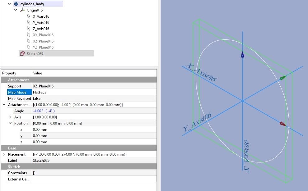
Here are some screenshots and a demo file.
offset_distance_at_anangle_demo.FCStd
(28.59 KiB) Downloaded 25 times
The cuboid is just created at Body origin to demonstrate the Body axis system, the cylinder is as Gene suggested and the prism is what you should have done.
Screenshot_20201023_100427.png
Screenshot_20201023_100427.png (14.39 KiB) Viewed 982 times
Jim

OS: Ubuntu 18.04.5 LTS (KDE/plasma)
Word size of OS: 64-bit
Word size of FreeCAD: 64-bit
Version: 0.19.
Build type: Release
Branch: unknown
Hash: 537089b34609308bdb11a8b139dbf013dc7e6ce3
Python version: 3.6.9
Qt version: 5.9.5
Coin version: 4.0.0a
OCC version: 7.3.0
Locale: English/Australia (en_AU)
Post Reply