Should be fixed.thschrader wrote: ↑Sun Dec 16, 2018 1:48 pm gmsh: works fine
cfmesh: meshing error at front-window
snappyhexmesh: gives allways a 3D-mesh (?)
2D-meshing in cfd
Moderator: oliveroxtoby
Forum rules
and Helpful information for the FEM forum
and Helpful information for the FEM forum
-
oliveroxtoby

- Posts: 837
- Joined: Fri Dec 23, 2016 9:43 am
- Location: South Africa
Re: 2D-meshing in cfd
Please provide all the information requested in this post before reporting problems with CfdOF.
Re: 2D-meshing in cfd
Hello,
After compute a 3D case, in which I have boundary layers sub mesh regions, I have only access after Extract Block command to "multiblock datatest and internal mesh". I cannot choose the boundaries of interest like in the tutorial you show me.
What should I do in FreeCAD to have access to the boundaries groups in Paraview ?
Best regards
Julien
Re: 2D-meshing in cfd
I do slightly differently, I don't know why:
I can have access to the boundaries directly in the first node of Paraview Openfoam reader.
After I do the same operation than in the tutorial and finally I integrate over the surface of interest the lift and drag forces, but I think that I have to multiply the pressure calculated by Openfoam by the volumic mass of my fluid [kg/m^3] ? Right?
Best regards
Julien
-
thschrader
- Veteran
- Posts: 3156
- Joined: Sat May 20, 2017 12:06 pm
- Location: Germany
Re: 2D-meshing in cfd
Hello,
I have a geometry that can be solved in 2D.
I try the 2Dboudingplane condition (try to assign the 2 planes in the same node or 2 nodes with 1 plane in each) but it doesn't work for the 3 meshers.
Is this option is still supported ?
Julien
I have a geometry that can be solved in 2D.
I try the 2Dboudingplane condition (try to assign the 2 planes in the same node or 2 nodes with 1 plane in each) but it doesn't work for the 3 meshers.

Is this option is still supported ?
Julien
-
thschrader
- Veteran
- Posts: 3156
- Joined: Sat May 20, 2017 12:06 pm
- Location: Germany
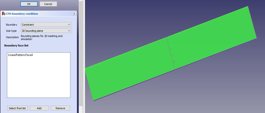
Re: 2D-meshing in cfd
assign each face as a separate BC.
- constraint.JPG (31.73 KiB) Viewed 1270 times
Re: 2D-meshing in cfd
Yes I have already done this
-
oliveroxtoby
- Posts: 837
- Joined: Fri Dec 23, 2016 9:43 am
- Location: South Africa
Re: 2D-meshing in cfd
Please upload your case, otherwise it's pure guesswork.
Please provide all the information requested in this post before reporting problems with CfdOF.
Re: 2D-meshing in cfd
The file is attached.
With the native geometry drawn with partdesign, I have several errors telling that I have to add 2Dbounding BC.
I have exported the geometry in step file and import it. I am able to run the snappyHexMesh in 2D but the result is completly wrong.
Someone can try to mesh this case in 2D please?
With the native geometry drawn with partdesign, I have several errors telling that I have to add 2Dbounding BC.
I have exported the geometry in step file and import it. I am able to run the snappyHexMesh in 2D but the result is completly wrong.
Someone can try to mesh this case in 2D please?
- Attachments
-
- Ailette_FC019_forum.FCStd
- (29.46 KiB) Downloaded 68 times
-
oliveroxtoby
- Posts: 837
- Joined: Fri Dec 23, 2016 9:43 am
- Location: South Africa
Re: 2D-meshing in cfd
Works for me with all three meshers if I use a base element size of 4mm. If you made the slab thicker, you could use a larger element size.julieng wrote: ↑Fri Nov 20, 2020 3:37 pm The file is attached.
With the native geometry drawn with partdesign, I have several errors telling that I have to add 2Dbounding BC.
I have exported the geometry in step file and import it. I am able to run the snappyHexMesh in 2D but the result is completly wrong.
Someone can try to mesh this case in 2D please?