Civil engineering feature implementation (Transportation Engineering)

Have some feature requests, feedback, cool stuff to share, or want to know where FreeCAD is going? This is the place.
Forum rules
Be nice to others! Read the FreeCAD code of conduct!
User avatar
microelly2
Veteran
Posts: 4688
Joined: Tue Nov 12, 2013 4:06 pm
Contact:

Re: Civil engineering feature implementation (Transportation Engineering)

Post by microelly2 »

griffmic88 wrote: Tue Mar 27, 2018 1:22 pm Image
We should have a list of such dialogs to "recreate" them as Pyside widgets. I use my miki class to create such objects form a simple text file.
http://freecadbuch.de/doku.php?id=blog: ... g_erzeugen

for the first steps I would use yaml format to store the data. yaml is easy to read and to modify.
Later the database format can be xml or a real sql database.
Following the MVC concept it is no problem to replace the database in later steps.

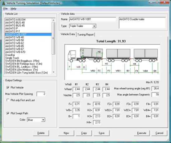
here is an other example
https://forum.freecadweb.org/viewtopic. ... 50#p161369
I will start a prototype of such a dialog this week.
User avatar
Joel_graff
Veteran
Posts: 1949
Joined: Fri Apr 28, 2017 4:23 pm
Contact:

Re: Civil engineering feature implementation (Transportation Engineering)

Post by Joel_graff »

A design question for griffmic88...
griffmic88 wrote: ping
So I've gotten my alignment tool to successfully insert a second curve next to an existing one. The question is.. how much construction geometry do I need?

If I build up a 3-center curve, it currently looks like this:
screenshot_1.png
screenshot_1.png (10.9 KiB) Viewed 1398 times
But I suspect it is probably sufficient if it is just this (it's a 2-center curve, I know..):
screenshot.png
screenshot.png (9.34 KiB) Viewed 1398 times

Obviously, I'd rather use less geometry - it makes for a lot less work down the road. I don't think there's a need to build the local / internal tangents.

Thoughts?
FreeCAD Trails workbench for transportation engineering: https://www.github.com/joelgraff/freecad.trails

pivy_trackers 2D coin3D library: https://www.github.com/joelgraff/pivy_trackers
griffmic88
Posts: 37
Joined: Mon Mar 05, 2018 3:18 pm
Contact:

Re: Civil engineering feature implementation (Transportation Engineering)

Post by griffmic88 »

Joel_graff wrote: Mon Apr 02, 2018 11:38 am A design question for griffmic88...
griffmic88 wrote: ping
So I've gotten my alignment tool to successfully insert a second curve next to an existing one. The question is.. how much construction geometry do I need?

If I build up a 3-center curve, it currently looks like this:

screenshot_1.png

But I suspect it is probably sufficient if it is just this (it's a 2-center curve, I know..):

screenshot.png


Obviously, I'd rather use less geometry - it makes for a lot less work down the road. I don't think there's a need to build the local / internal tangents.

Thoughts?

I see everything I would need to lay out the compound curve. I've only laid out about 6 or 7 in my short career lol. It would be awesome if your tool would label the alignment (aka with stationing and points of interest). Maybe when the alignment is sent to sheets?

Edit: I just saw the three center curve and yes, it would provide enough information to lay it out in the field.
User avatar
Joel_graff
Veteran
Posts: 1949
Joined: Fri Apr 28, 2017 4:23 pm
Contact:

Re: Civil engineering feature implementation (Transportation Engineering)

Post by Joel_graff »

griffmic88 wrote: Mon Apr 02, 2018 2:40 pm It would be awesome if your tool would label the alignment (aka with stationing and points of interest). Maybe when the alignment is sent to sheets?
That's something I've thought about and plan on having it as a part of the alignment design process, eventually.

As for the layout geometry, I can't imagine why the extra internal tangents would be needed. I think only the outermost tangents and the ability to set the curve center / radius is enough...
FreeCAD Trails workbench for transportation engineering: https://www.github.com/joelgraff/freecad.trails

pivy_trackers 2D coin3D library: https://www.github.com/joelgraff/pivy_trackers
griffmic88
Posts: 37
Joined: Mon Mar 05, 2018 3:18 pm
Contact:

Re: Civil engineering feature implementation (Transportation Engineering)

Post by griffmic88 »

Joel_graff wrote: Mon Apr 02, 2018 3:31 pm
griffmic88 wrote: Mon Apr 02, 2018 2:40 pm It would be awesome if your tool would label the alignment (aka with stationing and points of interest). Maybe when the alignment is sent to sheets?
That's something I've thought about and plan on having it as a part of the alignment design process, eventually.

As for the layout geometry, I can't imagine why the extra internal tangents would be needed. I think only the outermost tangents and the ability to set the curve center / radius is enough...
I typically keep them on geometric control and layout sheets, because as soon as you see multiple tangents you know what you are dealing with. I do keep the linestyle a little thinner though for the tangent lengths so they don't overlap or criss-cross more important information.

And I typically have a sheet for geometric data (like your line would need its positions indicated in some X,Y format).
User avatar
Joel_graff
Veteran
Posts: 1949
Joined: Fri Apr 28, 2017 4:23 pm
Contact:

Re: Civil engineering feature implementation (Transportation Engineering)

Post by Joel_graff »

griffmic88 wrote: Mon Apr 02, 2018 8:58 pm I typically keep them on geometric control and layout sheets, because as soon as you see multiple tangents you know what you are dealing with.
Don't suppose you can find an online example or something?

The internal tangent geometry is entirely unnecessary for the sketcher or the designer to accurately control the curve, but I can see where not having the local PI's for the individual curves might be a problem.
FreeCAD Trails workbench for transportation engineering: https://www.github.com/joelgraff/freecad.trails

pivy_trackers 2D coin3D library: https://www.github.com/joelgraff/pivy_trackers
User avatar
Joel_graff
Veteran
Posts: 1949
Joined: Fri Apr 28, 2017 4:23 pm
Contact:

Re: Civil engineering feature implementation (Transportation Engineering)

Post by Joel_graff »

Completely unrelated to this thread, but I know microelly will find it interesting.

It's a 15 minute video from blender con 2017 on using blender to build orthopedic joints.

https://www.google.com/url?sa=t&source= ... 67hHw_PQZL
Last edited by Joel_graff on Tue Apr 03, 2018 1:32 pm, edited 1 time in total.
FreeCAD Trails workbench for transportation engineering: https://www.github.com/joelgraff/freecad.trails

pivy_trackers 2D coin3D library: https://www.github.com/joelgraff/pivy_trackers
griffmic88
Posts: 37
Joined: Mon Mar 05, 2018 3:18 pm
Contact:

Re: Civil engineering feature implementation (Transportation Engineering)

Post by griffmic88 »

Joel_graff wrote: Mon Apr 02, 2018 9:09 pm
griffmic88 wrote: Mon Apr 02, 2018 8:58 pm I typically keep them on geometric control and layout sheets, because as soon as you see multiple tangents you know what you are dealing with.
Don't suppose you can find an online example or something?

The internal tangent geometry is entirely unnecessary for the sketcher or the designer to accurately control the curve, but I can see where not having the local PI's for the individual curves might be a problem.
Better yet, I'll make a quick example with what you can typically see. Sorry for the dual screen layout, but it's the only way to design with multiple screens.


EDIT: Now that I recall, I usually add sub tangents just so people can see the differing radii.
Image
User avatar
Joel_graff
Veteran
Posts: 1949
Joined: Fri Apr 28, 2017 4:23 pm
Contact:

Re: Civil engineering feature implementation (Transportation Engineering)

Post by Joel_graff »

griffmic88 wrote: Tue Apr 03, 2018 1:20 pm Now that I recall, I usually add sub tangents just so people can see the differing radii.
Your example only uses single center curves. :) Of course, most alignments won't ever use compound curves, but they're too useful to just ignore for the time being.

The problem is, subtangents create clutter visually and really, provide too much control... But seeing each arc's PI does make it easier to visually assess the alignment's design.

Essentially, I'd view the subtangents as "read-only" geometry... though mostly, I just don't want to have to manage it in script...

Oy.

Edit: maybe the major PI isn't necessary?
FreeCAD Trails workbench for transportation engineering: https://www.github.com/joelgraff/freecad.trails

pivy_trackers 2D coin3D library: https://www.github.com/joelgraff/pivy_trackers
griffmic88
Posts: 37
Joined: Mon Mar 05, 2018 3:18 pm
Contact:

Re: Civil engineering feature implementation (Transportation Engineering)

Post by griffmic88 »

Joel_graff wrote: Tue Apr 03, 2018 1:47 pm
griffmic88 wrote: Tue Apr 03, 2018 1:20 pm Now that I recall, I usually add sub tangents just so people can see the differing radii.
Your example only uses single center curves. :) Of course, most alignments won't ever use compound curves, but they're too useful to just ignore for the time being.

The problem is, subtangents create clutter visually and really, provide too much control... But seeing each arc's PI does make it easier to visually assess the alignment's design.

Essentially, I'd view the subtangents as "read-only" geometry... though mostly, I just don't want to have to manage it in script...

Oy.

Edit: maybe the major PI isn't necessary?
O I see now where you wanted to see a compound curve....let me go get my morning coffee..our thread is getting long lol.
Post Reply