Hello,
I have a problem with the Dimension tool. In the Draft workbench, I can't create vertical dimensions (using the Dimension tool with the Shift key) in XZ and YZ working plane, only in XY (top) plane. But horizontal dimensions work in all three planes. In XZ and YZ planes, vertical dimension disappears during its creation with the Shift key, and the result is a weird dimension connected to the 3D origin. So for example, I can't create a parametric vertical dimension of a slanted roof in the Arch workbench. I know about the principle "clicking Shift while the pointer is close or far from the first point", but it helps only in the XY plane.
Switch to the Draft workbench, Utilities -> SelectPlane -> Front (XZ), View -> Standard views -> Front, select the Dimension tool, pick the first point anywhere, pick the second point of an imaginary slanted line, hold the Shift key and move the mouse pointer and try to create a vertical dimension of the slanted line. You can create only a horizontal dimension. Tested in the last FreeCAD 0.18.4 and 0.19 (20209).
OS: Linux Mint 19.3 (X-Cinnamon/cinnamon)
Word size of OS: 64-bit
Word size of FreeCAD: 64-bit
Version: 0.19.20209 (Git) AppImage
Build type: Release
Branch: master
Hash: 5fc4a26a00390e91cbf91848b766b68ad87e5917
Python version: 3.8.2
Qt version: 5.12.5
Coin version: 4.0.0
OCC version: 7.4.0
Locale: English/United States (en_US)
Vertical dimensions can't be created in XZ and YZ working plane
Forum rules
Be nice to others! Read the FreeCAD code of conduct!
Be nice to others! Read the FreeCAD code of conduct!
Re: Vertical dimensions can't be created in XZ and YZ working plane
Hello and welcome to the forum.
May I ask you if you changed the working plane before creating the dimension?
Also it would be helpful if you could post a screenshot of the dimension that fails.
Thanks!
May I ask you if you changed the working plane before creating the dimension?
Also it would be helpful if you could post a screenshot of the dimension that fails.
Thanks!
follow my experiments on BIM modelling for architecture design
Re: Vertical dimensions can't be created in XZ and YZ working plane
Yeah, the word censored modifier is a bit tricky, and I guess it hasn't been tested in all cases. I don't think a lot of people use it or even know about it.
My suggestion in that case is to use the X or Y keys in your keyboard in order to constraint the dimension to be horizontal or vertical, as you need, to position the second point. Then when you drag the dimension, it will be created vertically or horizontally.
Always add the important information to your posts if you need help. Also see Tutorials and Video tutorials.
To support the documentation effort, and code development, your donation is appreciated: liberapay.com/FreeCAD.
To support the documentation effort, and code development, your donation is appreciated: liberapay.com/FreeCAD.
Re: Vertical dimensions can't be created in XZ and YZ working plane
Yes, I can use X or Y keys to draw a horizontal or vertical dimension. I can also pick the first point, hold the Shift key and pick the second point to create a horizontal or vertical dimension. It works, but it will not be parametric, so if I change the object, the dimension will not change. To be parametric, I have to select a line instead of points, but then X or Y keys won't help.
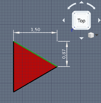
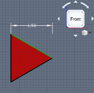
OK, I took two screenshots. On the first screenshot, it's in the XY (top) working plane. I select the green line, then I draw horizontal and vertical parametric dimensions. On the second screenshot, it's the XZ (front) plane. I select the green line, then I draw the horizontal parametric dimension, but I can't draw the vertical parametric dimension.
I've noticed another problem. As you can see on the second screenshot in the XZ (front) plane, text is over the dimension line, but the Data -> Text Spacing is 50 mm, so it should be moved up, but it's moved down and I can't set a negative value. In the XY (top) plane, it's OK with the same Text Spacing (the first screenshot). Moreover, I had to use Draft -> Utilities -> Flip Dimension, which is quite hidden, so I think Flip Dimension should be in Data. For example Flip Text is there.
Re: Vertical dimensions can't be created in XZ and YZ working plane
indeed there is something strange.
About fliptext parameter, here is the ongoing rearrangement of dimension view parameters. Since it's something related to the view object, it can't go into Data tab
I can have a look after the pending PR on dimension styles is merged.
About fliptext parameter, here is the ongoing rearrangement of dimension view parameters. Since it's something related to the view object, it can't go into Data tab
- Cattura.JPG (44.69 KiB) Viewed 1760 times
follow my experiments on BIM modelling for architecture design
Re: Vertical dimensions can't be created in XZ and YZ working plane
Yes, Flip Text is in the View tab, not in Data. Sorry, I mixed it up. In my previous post, I wanted to write: "I had to use Draft -> Utilities -> Flip Dimension, which is quite hidden, so I think Flip Dimension should be in View. For example Flip Text is there." Because in the Front plane, my dimension text (in the second screenshot) was backwards (which is a bit weird, but no problem here).
Re: Vertical dimensions can't be created in XZ and YZ working plane
I've noticed another strange behaviour (tested in the last FreeCAD 0.18 and 0.19):
Start FreeCAD, create a new document, switch to the Draft workbench, draw a dimension. Try to choose the Font Name "osifont" in the View tab. It's not available.
Start FreeCAD, create a new document, switch to the TechDraw workbench, switch to the Draft workbench, draw a dimension. Try to choose the Font Name "osifont" in the View tab. It's available.
Re: Vertical dimensions can't be created in XZ and YZ working plane
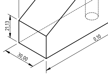
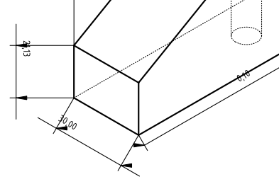
And another one: I created a simple model, then I created its isometric drawing in TechDraw in FreeCAD 0.18. It's OK, on the first screenshot. Then I saved it and opened it in the last FreeCAD 0.19. It's on the second screenshot. Some dimension lines are longer or shorter, some have wrong directions, all arrows are horizontal, text is smaller and sometimes in wrong position.
Re: Vertical dimensions can't be created in XZ and YZ working plane
Font selectors of Draft dimension/annotaion have known bugs, only few fonts can be applied.Lukas1 wrote: ↑Tue Mar 24, 2020 7:28 pm I've noticed another strange behaviour (tested in the last FreeCAD 0.18 and 0.19):
Start FreeCAD, create a new document, switch to the Draft workbench, draw a dimension. Try to choose the Font Name "osifont" in the View tab. It's not available.
Start FreeCAD, create a new document, switch to the TechDraw workbench, switch to the Draft workbench, draw a dimension. Try to choose the Font Name "osifont" in the View tab. It's available.
Re: Vertical dimensions can't be created in XZ and YZ working plane
OK, I understand. But it's strange that it works better if TechDraw is selected before Draft. So if I want to use osifont in Draft, I have to select TechDraw, then Draft and it works.