Dear Mr. Daniel Falck,
I'm Angelo Bertocchi, an Italian mechanical engineer with the passion
for calculation and computer programming.
I received your message regarding my web application - mebac.
Me-Bac/Spur Gears is a free tool to create and to calculate spur gears
and to export the dxf profile of the gears.
In past I saw commercial cad tools that were not accurate generating the
gears: this is the reason why I created this app.
Yes, it's related to FreeCad bacause it's a tool that can be used in
conjunction with cad software, useful for designers, engineers, students.
If you have other questions, please contact me.
Thanks for your attention and best regards.
Angelo
FCGear: a gear generator using Bezier curves
Forum rules
Be nice to others! Respect the FreeCAD code of conduct!
Be nice to others! Respect the FreeCAD code of conduct!
[OnHold]Re: FCGear: a gear generator using Bezier curves
You could also use the free web app at http://www.me-bac.com to create the spur gear profile. Best regards.

Re: [OnHold]Re: FCGear: a gear generator using Bezier curves
Though i prefer to have gear generation integrated as tightly as possible, i see a great feature.mebac wrote:You could also use the free web app at http://www.me-bac.com to create the spur gear profile.
Your web app supports profile shift
Re: [OnHold]Re: FCGear: a gear generator using Bezier curves
Yes, it’s possible to create standard and corrected spur gears.shoogen wrote:Though i prefer to have gear generation integrated as tightly as possible, i see a great feature.mebac wrote:You could also use the free web app at http://www.me-bac.com to create the spur gear profile.
Your web app supports profile shift
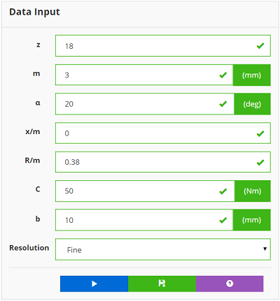
For example, consider a m=3 standard gear:
a=20°
x/m=0
R/m=0.38
For this gear, the minimum number of teeth is 18 - to not have geometric undercut effects.
To evaluate the tooth root bending stress, consider also a gear face-width equal to 10 mm and an applied static torque of 50 Nm.
Here is the input data.
And this is the corresponding gear.
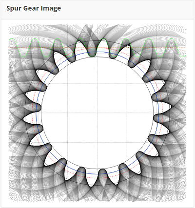
In the results table you could find a lot of useful information concerning the gear: e.g. geometric data, the minimum and maximum shift coefficient, the tooth root bending stress (186.03 N/mm2), etc.
For specific applications, if you need to reduce the number of teeth – for example z=16 – you have to correct the gear, modifying the x/m parameter.
You can realize a gear with z=16 and alfa=20° with the following input data

And this is the corresponding gear.
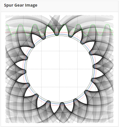
In the result table, the tooth root bending stress is 156.88 N/mm2.
Of course you can download the DXF profiles of the gears and use them with FreeCAD
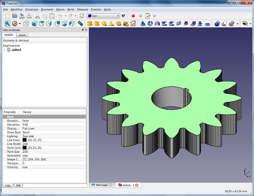
B.R.