
I chatted with Stephen some time ago about this, that's probably where the FreeCAD support idea comes from...
However, this is a Blender plugin, and Stephen is a Blender developer, so this probably won't happen quickly or easily.
I think we should start on our side to make a Blender exporter that takes Blender meshes and produces FreeCAD Parts.
It's actually not very hard, my only blocking problem so far is how to get regions of coplanar faces from a Blender mesh...
Once that is done, the problem of adding some parametrics will become greatly simplified
BIM/Arch development news articles from Yorik's blog
Forum rules
Be nice to others! Respect the FreeCAD code of conduct!
Be nice to others! Respect the FreeCAD code of conduct!
Re: BIM/Arch development news articles from Yorik's blog
It happens @Vocx quote @Yorik's earlier dicussion here and note @Yorik had not cross-posted his 2 blogs here
FreeCAD BIM development news - December 2019/January 2020
FreeCAD BIM development news - October/November 2019
FreeCAD BIM development news - December 2019/January 2020
FreeCAD BIM development news - October/November 2019
Re: BIM/Arch development news articles from Yorik's blog
cross-posting from https://yorik.uncreated.net/blog/2020-0 ... uary-march
FreeCAD BIM development news - February/March 2020
Hi everybody!
High time for a new update about the development of BIM tools for FreeCAD. Once again, sorry for the lag since last update, no need to explain I guess, everyone is having the same kind of struggle. Between the coronavirus confinement and my move to Europe, which I was able to do just in time, things got a bit wacky.
The good news is, I am now well settled in Belgium, and decided to get back as much as possible to FreeCAD. I really miss coding and spending time with it, and currently orienting things to be able to do more of it again, and possibly, who knows, make it my main occupation.
As always, thanks so much to everybody who supports me (and demonstrates patience!) on Patreon or Liberapay! I hope in the near future we can harness new levels and help making the use of FreeCAD as a BIM platform explode!
So here is a short overview of what I've been working with this month:
BIM templates
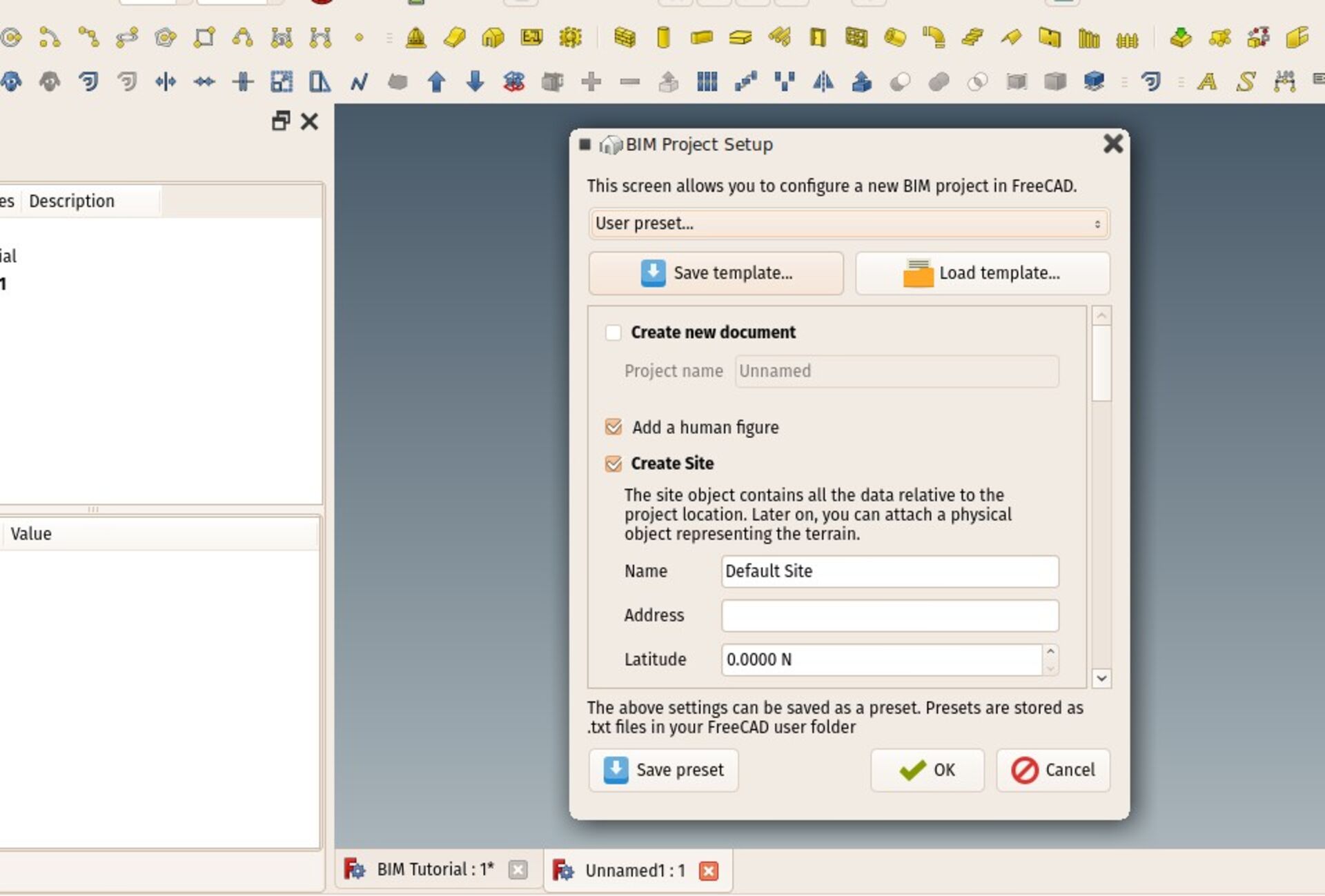
The BIM Project tool has now been extended to support file-based templates. The system is rather simple: On saving a template, the active document is saved as a standard FreeCAD file, including all the current workspace settings such as working plane position or units settings. On restoring a template, its contents (if any) will be merged into the current document, and the stored settings applied.
I'm quite happy with this simple thing as it works in a way more flexible manner than most templates found in other BIM applications: Here, you can apply a template AFTER starting a file.
Saving working space settings is in my humble opinion not so useful, as in FreeCAD there is not much "preparation" needed before starting to model, and you usually switch these things all the time, and they are easy to manipulate, but having a way to store some "libraries" of objects somewhere and be able to recall them anytime into your project when you need them seems an awesome feature to have.
BIM library online mode
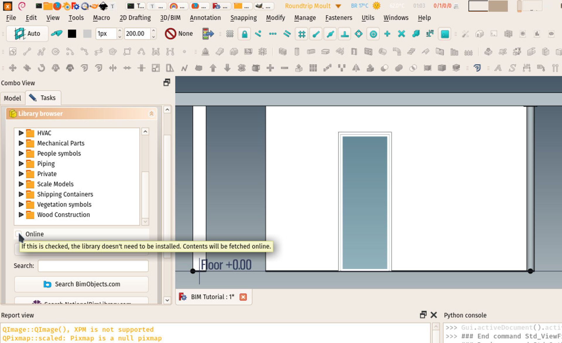
The BIM Library tool, that allows you to insert in your model elements from the FreeCAD parts library, now has an online mode, that you can switch on/off. When off, the tool works as before: The parts library must be installed from the FreeCAD addons manager, and the library tool relies on it. You can keep the library updated with the addons manager.
In online mode, you don't need to install the library. Its contents are fetched directly from the online GIT repository. However, browsing the entire library via the web takes a couple of seconds and placing takes time because files need to be downloaded. We might also be limited by the Github API, so for now it works but I keep it under watch.
Updated BIM documentation
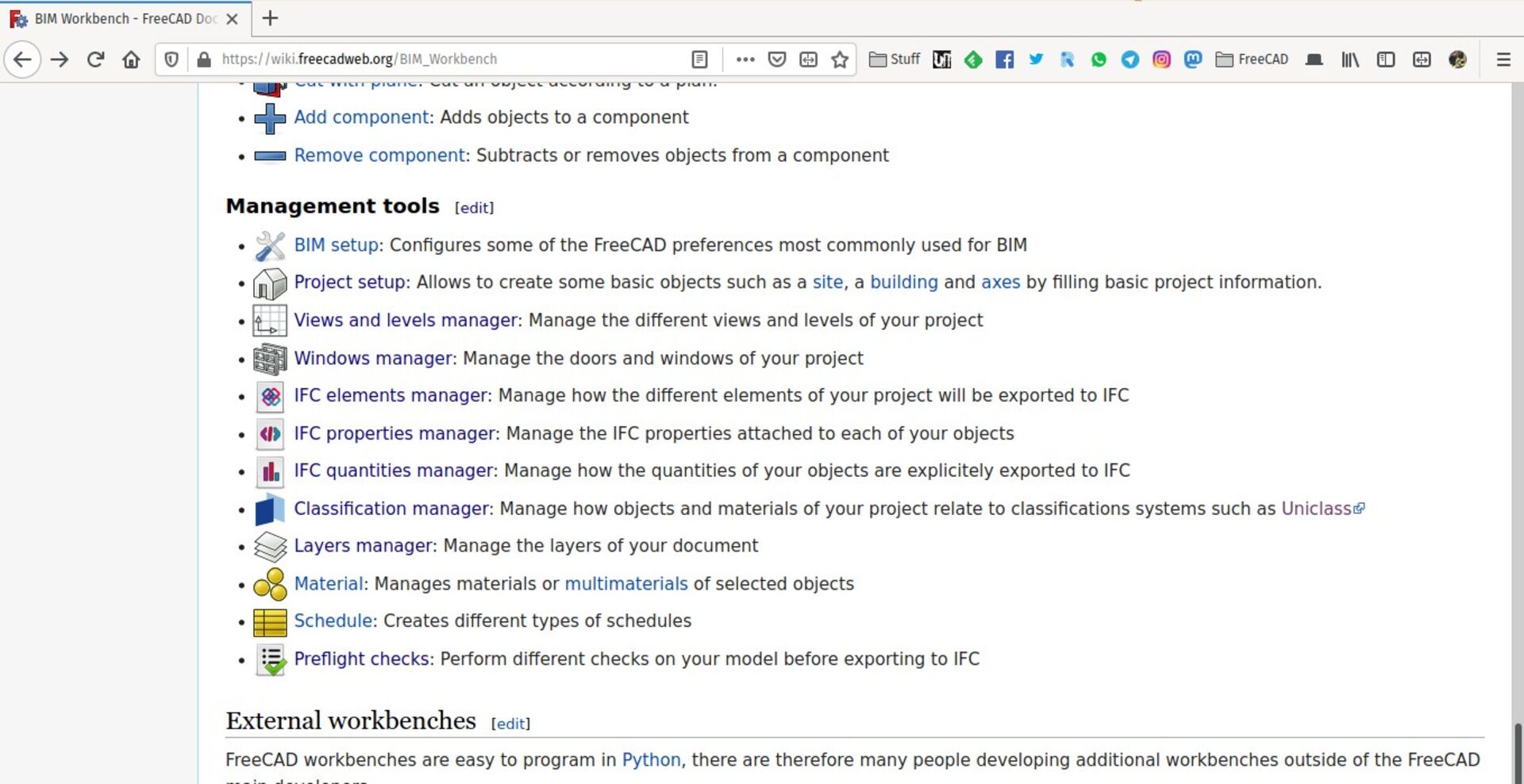
The documentation of the BIM workbench is now finally complete and fully up-to-date. I'll do my best to keep it that way from now on!
BIM tutorial
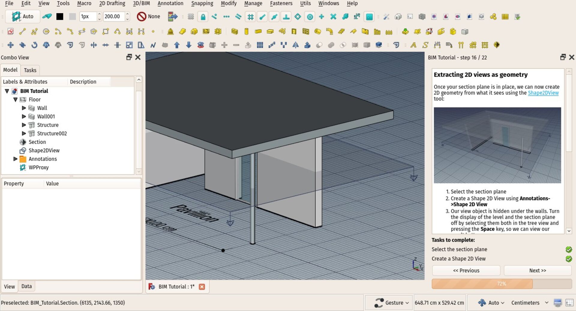
The BIM in-game tutorial, that you find inside the BIM workbench and that walks you through the different steps to find your marks with the BIM workbench, is almost complete now. You can launch it from within FreeCAD, from menu **Help -> BIM tutorial**.
There are just a few paragraphs missing, basically one to show how to use the TechDraw workbench to produce printable 2D documents, and one to manage IFC properties of your objects.
Custom tests in BIM preflight
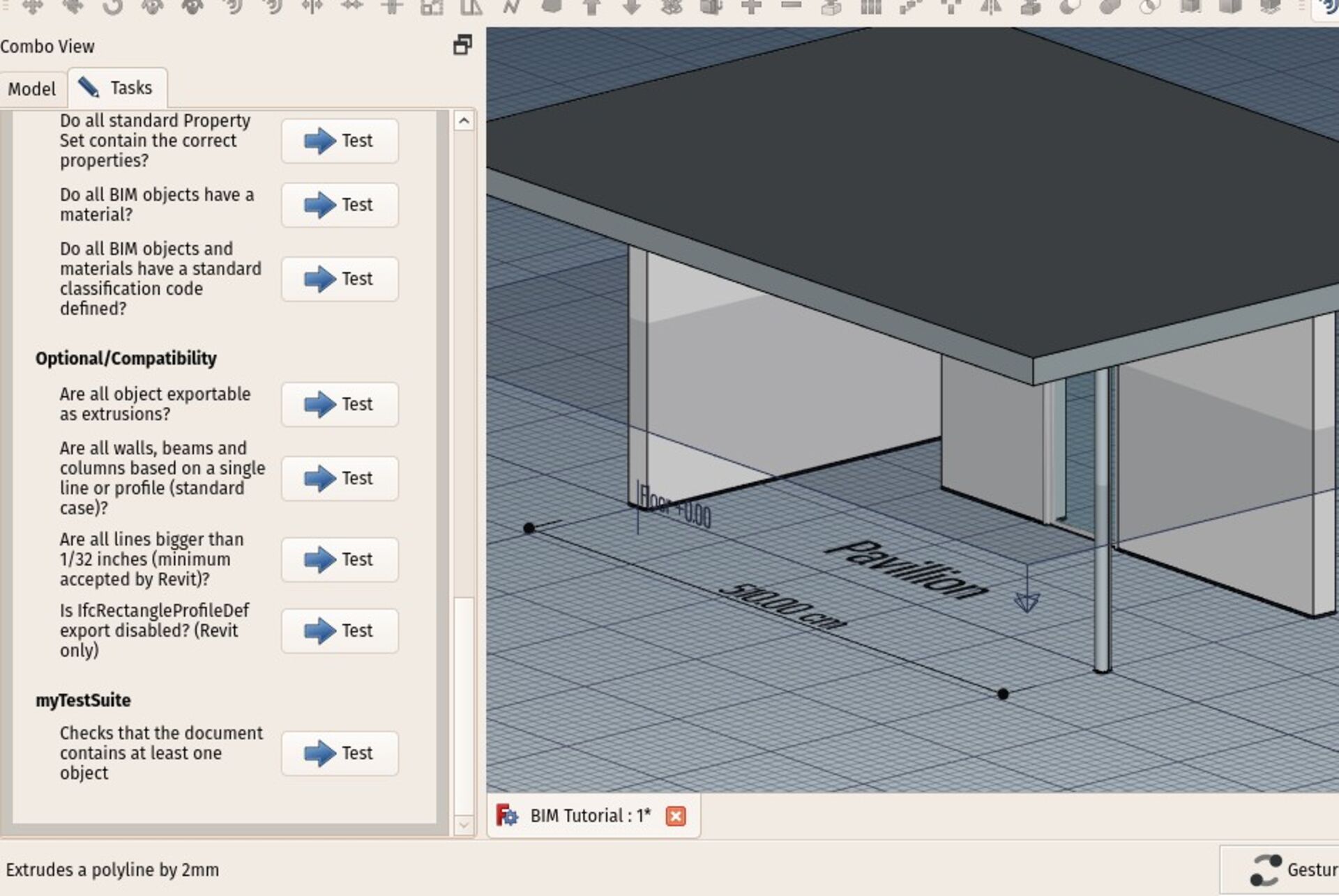
The BIM Preflight tool has been upgraded to support custom tests. This tool allows you to perform a series of tests on your model before exporting to IFC, to detect issues that could make your model less compatible or conform to standards.
Now, you can write your own tests too. These are pretty simple to write in Python, they are just simple functions that must pass or fail. This can allow a BIM team, for example, to setup rules, and to setup rules that verify that the rules were applied to the model.
Would we now need a kind of "certificate" system that a certain model passed the tests? What's yor idea on that? Don't hesitate to give your ideas.
Level manager
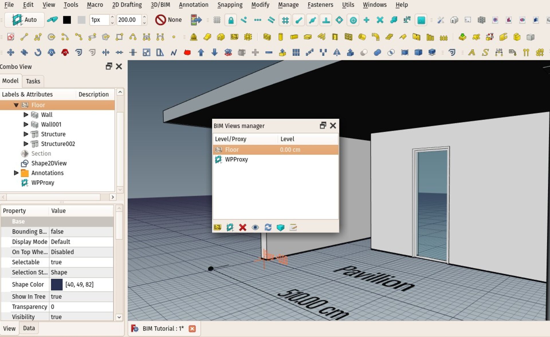
The Views and levels manager has been upgraded a bit, with new buttons and tools. You can now change the height of a level on the fly, or rename it, making it a much more interesting levels manager.
There is more work to be done on this widget so it can really become a good structure view of your model and allow to manage the whole thing in one simpler place than the tree view. But I think we are getting there.
Top, Front, Side working plane shortcuts
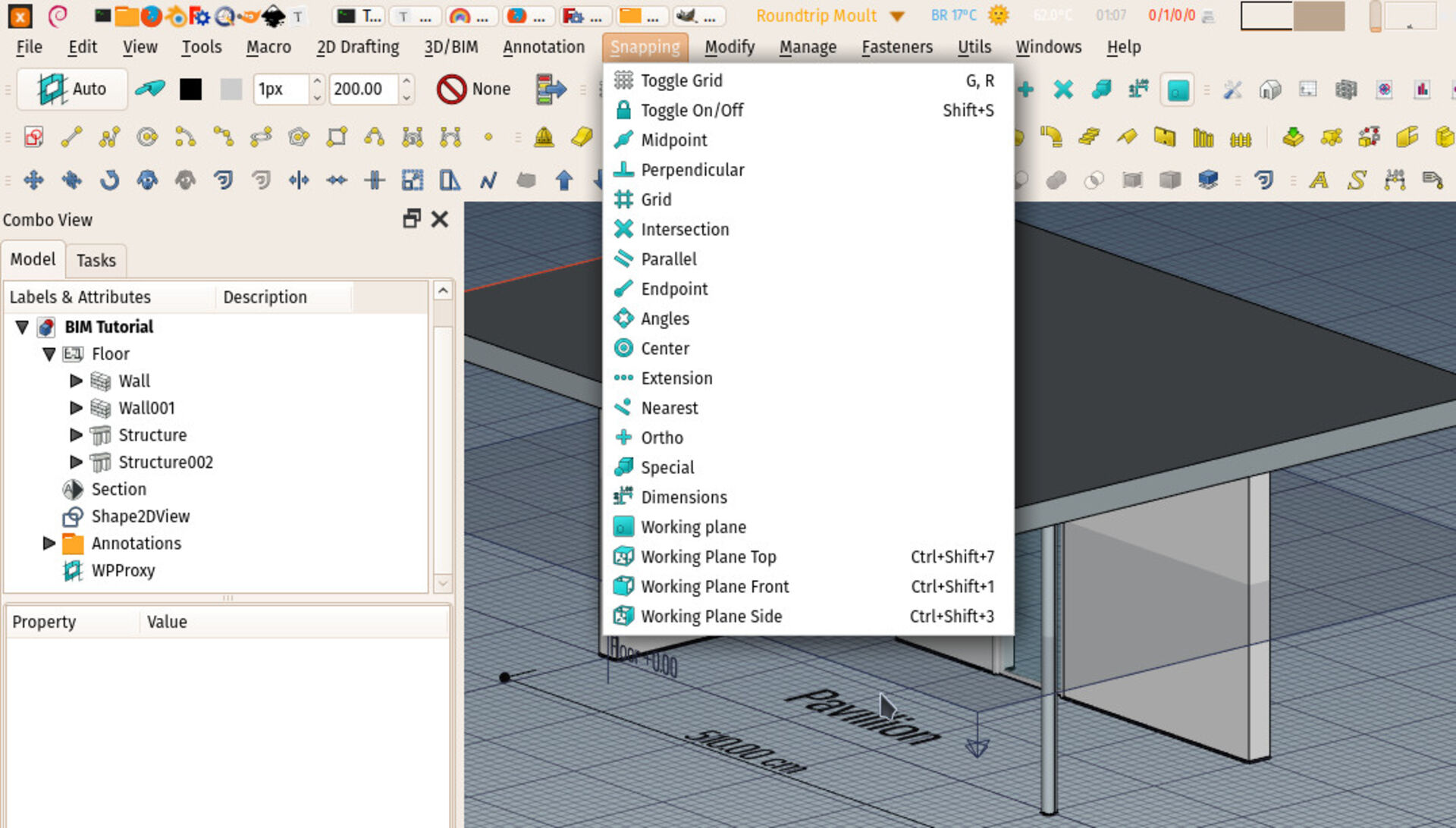
In the Bim Workbench, under the **snap** menu are now three new commands to set the working plane to Top, Front and Side positions. This is specially convenient to use from keyboard shortcuts, so you spare yourself a few clicks.
Pipe tool improvement
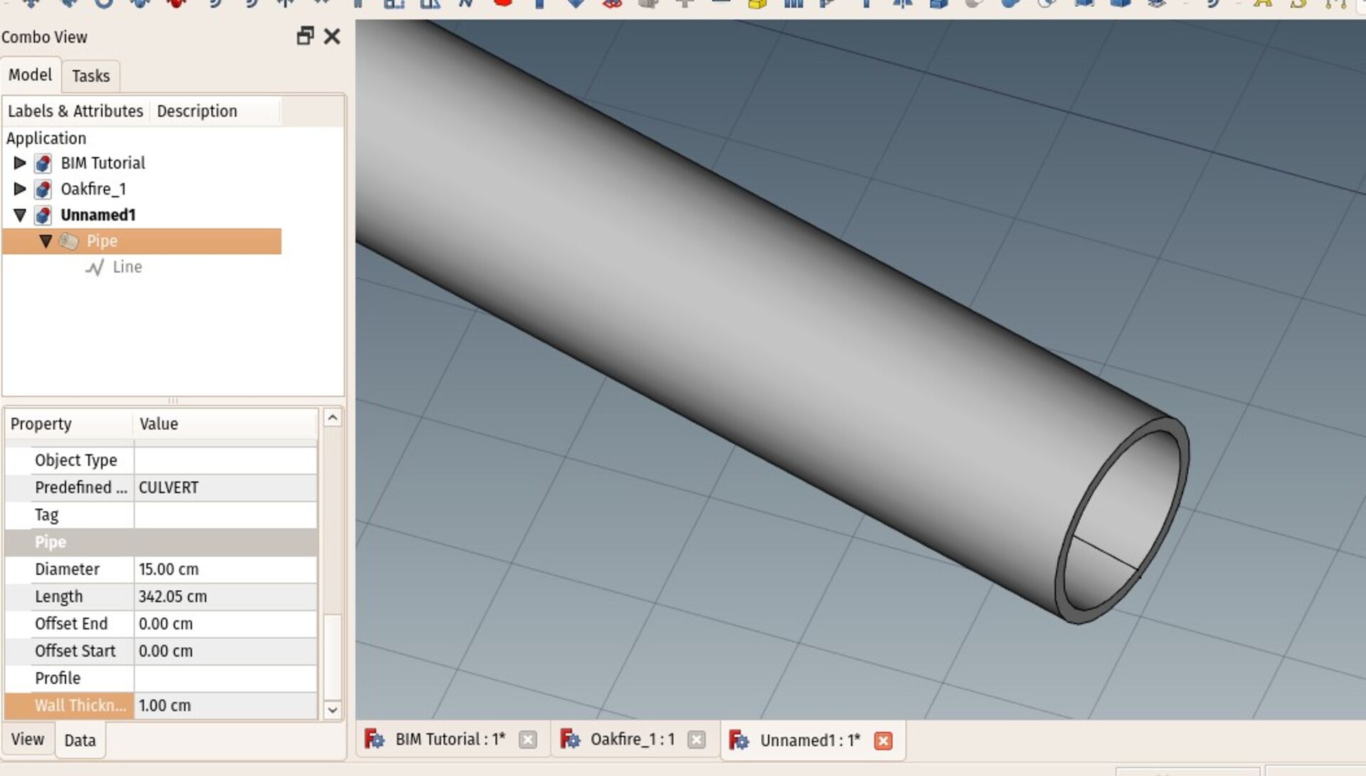
The Pipe tool has gained one new property called **Wall Thickness** that allows to specify the thickness of the material the tube is made of, which effectively makes the tube hollow. This makes working with tubes more realistic, although it might also add unnecessary detail and make the model heavier. Keeping the wall thickness to zero makes the tube fully filled, like it was before.
IFC export of ortho arrays
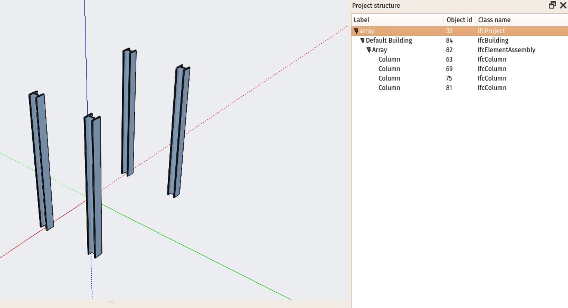
The IFC exporter now supports Orthogonal arrays. The array object itself is exported as an IfcElementAssembly, and its subobjects as clones. This reproduces more or less the same behaviour as the array, where each copy is an instance of the original object, but the arraying information is lost, as unfortunately the IFC standard doesn't provide a structure for instantiated arrays.
More array types will be supported later on, but I thought I'd start with one case to see if it works well.
IFC export of App Parts
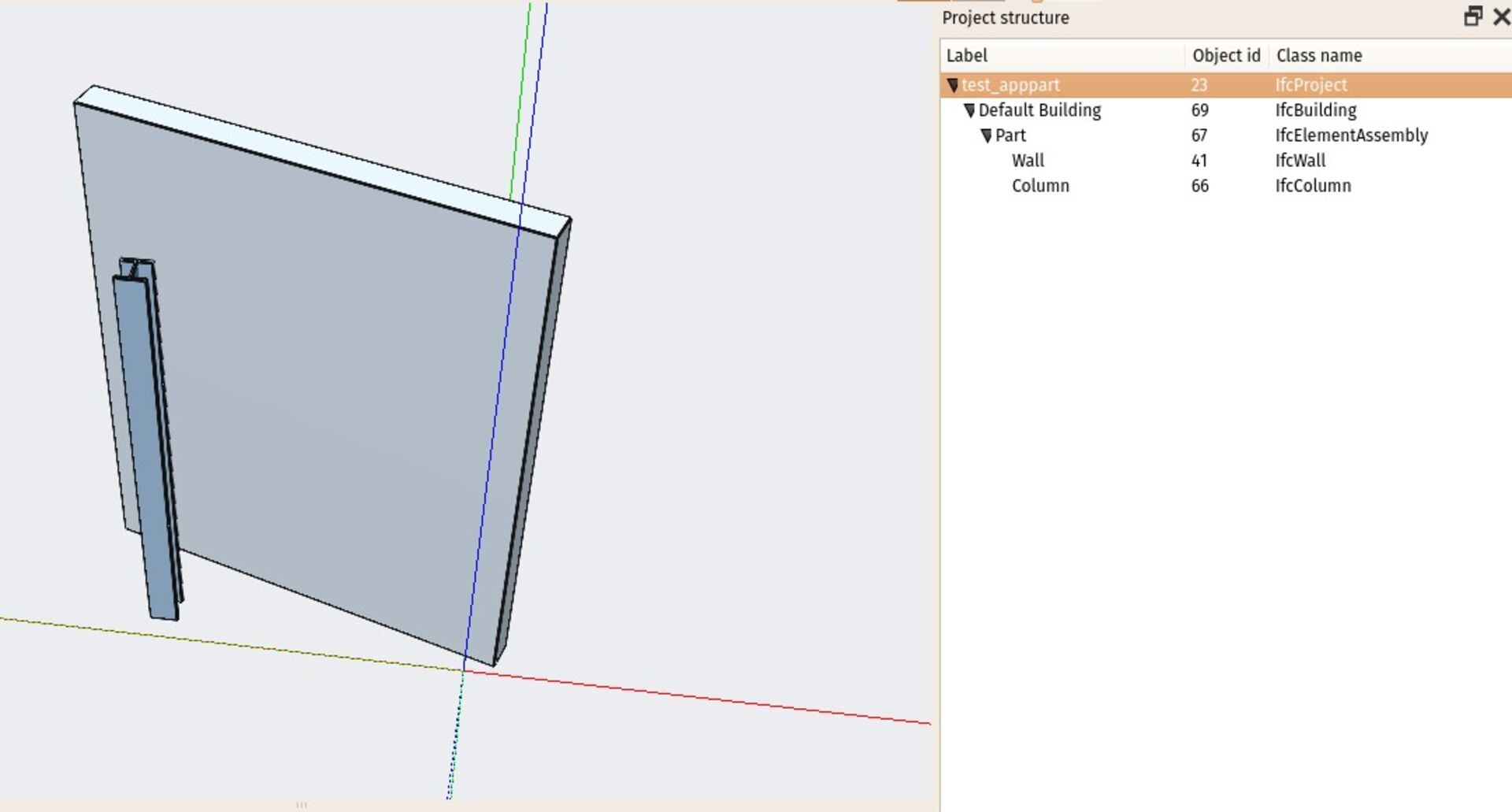
App Parts are a special type of object container in FreeCAD, similar to groups or building parts. They are still not widely used in BIM workflows, but have their advantages too, as they are more simple than building parts, but have more features than groups. Think of them as a group that moves its children when moved, and defines relative coordinates (the placement of the children remain unchanged even after moving the part).
App Parts are now supported at IFC export. They are also exported as IfcElementAssembly objects.
Custom Property Sets in IFC Properties Manager
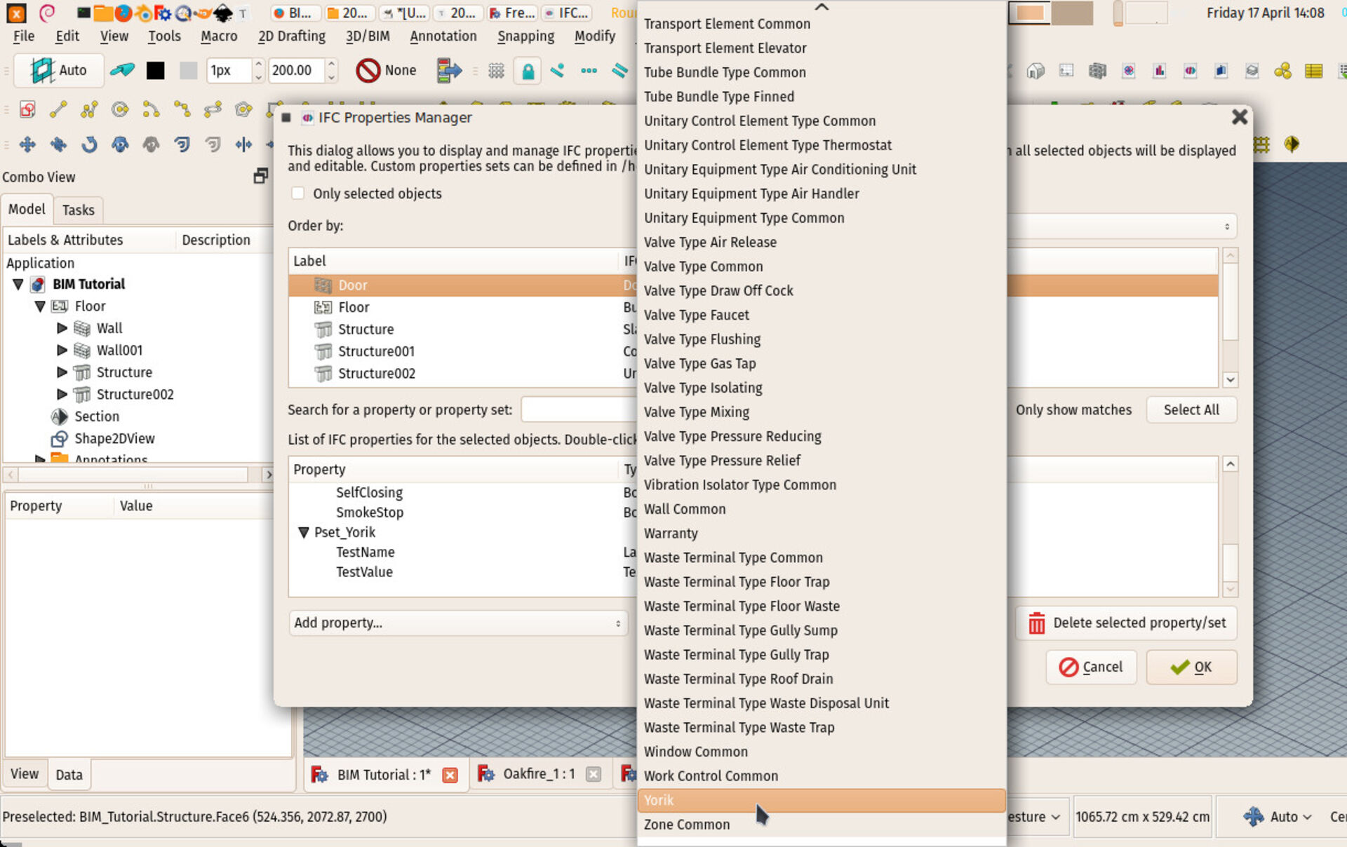
The IFC properties manager now allows you to define your own property sets, which can then easily be added to your objects from the property manager tool.
Misc other improvements
That is only the part I've been working on myself, but others are very active on other places of FreeCAD, and many improvements are coming everywhere else. What we call "the big merge", which was the merging of Realthunder's code that added the App Link system, which caused quite some instability in FreeCAD because of its magnitude, is now mostly stabilized (grab a 0.19 preview build to test, it's now very stable), and huge work is being done to refactor and extend the Draft workbench, which is one of the base pieces of the BIM workbench. Other workbenches such as FEM, TechDraw or Path have also seen very active development.
A little bit about the future
Several of us also think that with the fast growth, FreeCAD is coming to a point where the project and community as a whole are getting difficult to manage. Also, FreeCAD begins to interest companies, and its current loose, community-based only structure fails to provide what companies need (contact points, "official" communication channels, and official sponsoring possibilities).
Although it is of uttermost importance to everybody involved in the project to make sure FreeCAD continues absolutely free of any influence of the commercial world, and its developers free to develop in any direction and pace they want, without any form of pressure or direction, we also think there could exist a new "layer" on top of the FreeCAD development itself, that could provide that better interface, and possibly could receive sponsoring and help developers to feel more comfortable or do more or a better job. It is still not clear how this could exist, but we have started thinking.
Also being myself in Europe now is an excellent opportunity to dig into this further and connect to other projects, gather ideas, etc.
I think that's it for this edition, thanks for reading, and see you next month!
FreeCAD BIM development news - February/March 2020
Hi everybody!
High time for a new update about the development of BIM tools for FreeCAD. Once again, sorry for the lag since last update, no need to explain I guess, everyone is having the same kind of struggle. Between the coronavirus confinement and my move to Europe, which I was able to do just in time, things got a bit wacky.
The good news is, I am now well settled in Belgium, and decided to get back as much as possible to FreeCAD. I really miss coding and spending time with it, and currently orienting things to be able to do more of it again, and possibly, who knows, make it my main occupation.
As always, thanks so much to everybody who supports me (and demonstrates patience!) on Patreon or Liberapay! I hope in the near future we can harness new levels and help making the use of FreeCAD as a BIM platform explode!
So here is a short overview of what I've been working with this month:
BIM templates
The BIM Project tool has now been extended to support file-based templates. The system is rather simple: On saving a template, the active document is saved as a standard FreeCAD file, including all the current workspace settings such as working plane position or units settings. On restoring a template, its contents (if any) will be merged into the current document, and the stored settings applied.
I'm quite happy with this simple thing as it works in a way more flexible manner than most templates found in other BIM applications: Here, you can apply a template AFTER starting a file.
Saving working space settings is in my humble opinion not so useful, as in FreeCAD there is not much "preparation" needed before starting to model, and you usually switch these things all the time, and they are easy to manipulate, but having a way to store some "libraries" of objects somewhere and be able to recall them anytime into your project when you need them seems an awesome feature to have.
BIM library online mode
The BIM Library tool, that allows you to insert in your model elements from the FreeCAD parts library, now has an online mode, that you can switch on/off. When off, the tool works as before: The parts library must be installed from the FreeCAD addons manager, and the library tool relies on it. You can keep the library updated with the addons manager.
In online mode, you don't need to install the library. Its contents are fetched directly from the online GIT repository. However, browsing the entire library via the web takes a couple of seconds and placing takes time because files need to be downloaded. We might also be limited by the Github API, so for now it works but I keep it under watch.
Updated BIM documentation
The documentation of the BIM workbench is now finally complete and fully up-to-date. I'll do my best to keep it that way from now on!
BIM tutorial
The BIM in-game tutorial, that you find inside the BIM workbench and that walks you through the different steps to find your marks with the BIM workbench, is almost complete now. You can launch it from within FreeCAD, from menu **Help -> BIM tutorial**.
There are just a few paragraphs missing, basically one to show how to use the TechDraw workbench to produce printable 2D documents, and one to manage IFC properties of your objects.
Custom tests in BIM preflight
The BIM Preflight tool has been upgraded to support custom tests. This tool allows you to perform a series of tests on your model before exporting to IFC, to detect issues that could make your model less compatible or conform to standards.
Now, you can write your own tests too. These are pretty simple to write in Python, they are just simple functions that must pass or fail. This can allow a BIM team, for example, to setup rules, and to setup rules that verify that the rules were applied to the model.
Would we now need a kind of "certificate" system that a certain model passed the tests? What's yor idea on that? Don't hesitate to give your ideas.
Level manager
The Views and levels manager has been upgraded a bit, with new buttons and tools. You can now change the height of a level on the fly, or rename it, making it a much more interesting levels manager.
There is more work to be done on this widget so it can really become a good structure view of your model and allow to manage the whole thing in one simpler place than the tree view. But I think we are getting there.
Top, Front, Side working plane shortcuts
In the Bim Workbench, under the **snap** menu are now three new commands to set the working plane to Top, Front and Side positions. This is specially convenient to use from keyboard shortcuts, so you spare yourself a few clicks.
Pipe tool improvement
The Pipe tool has gained one new property called **Wall Thickness** that allows to specify the thickness of the material the tube is made of, which effectively makes the tube hollow. This makes working with tubes more realistic, although it might also add unnecessary detail and make the model heavier. Keeping the wall thickness to zero makes the tube fully filled, like it was before.
IFC export of ortho arrays
The IFC exporter now supports Orthogonal arrays. The array object itself is exported as an IfcElementAssembly, and its subobjects as clones. This reproduces more or less the same behaviour as the array, where each copy is an instance of the original object, but the arraying information is lost, as unfortunately the IFC standard doesn't provide a structure for instantiated arrays.
More array types will be supported later on, but I thought I'd start with one case to see if it works well.
IFC export of App Parts
App Parts are a special type of object container in FreeCAD, similar to groups or building parts. They are still not widely used in BIM workflows, but have their advantages too, as they are more simple than building parts, but have more features than groups. Think of them as a group that moves its children when moved, and defines relative coordinates (the placement of the children remain unchanged even after moving the part).
App Parts are now supported at IFC export. They are also exported as IfcElementAssembly objects.
Custom Property Sets in IFC Properties Manager
The IFC properties manager now allows you to define your own property sets, which can then easily be added to your objects from the property manager tool.
Misc other improvements
That is only the part I've been working on myself, but others are very active on other places of FreeCAD, and many improvements are coming everywhere else. What we call "the big merge", which was the merging of Realthunder's code that added the App Link system, which caused quite some instability in FreeCAD because of its magnitude, is now mostly stabilized (grab a 0.19 preview build to test, it's now very stable), and huge work is being done to refactor and extend the Draft workbench, which is one of the base pieces of the BIM workbench. Other workbenches such as FEM, TechDraw or Path have also seen very active development.
A little bit about the future
Several of us also think that with the fast growth, FreeCAD is coming to a point where the project and community as a whole are getting difficult to manage. Also, FreeCAD begins to interest companies, and its current loose, community-based only structure fails to provide what companies need (contact points, "official" communication channels, and official sponsoring possibilities).
Although it is of uttermost importance to everybody involved in the project to make sure FreeCAD continues absolutely free of any influence of the commercial world, and its developers free to develop in any direction and pace they want, without any form of pressure or direction, we also think there could exist a new "layer" on top of the FreeCAD development itself, that could provide that better interface, and possibly could receive sponsoring and help developers to feel more comfortable or do more or a better job. It is still not clear how this could exist, but we have started thinking.
Also being myself in Europe now is an excellent opportunity to dig into this further and connect to other projects, gather ideas, etc.
I think that's it for this edition, thanks for reading, and see you next month!

Re: BIM/Arch development news articles from Yorik's blog
Yaaay! Welcome to this articles.
Have you tested it with windows? In my case the problem are the images of the tutorial that are not loaded...
Is there a way to generate an unique hash for a FreeCAD file? With a hash that is linked only with the original file, you can use it to put in a digital document or report from the test system with a time stamp as certificate of the file status.
::bitacovir::
==================
One must be absolutely modern.
Arthur Rimbaud (A Season in Hell -1873)
Canal Youtube Grupo Telegram de FreeCAD Español
My personal web site
My GitHub repository
Mini Airflow Tunnel Project
==================
One must be absolutely modern.
Arthur Rimbaud (A Season in Hell -1873)
Canal Youtube Grupo Telegram de FreeCAD Español
My personal web site
My GitHub repository
Mini Airflow Tunnel Project
Re: BIM/Arch development news articles from Yorik's blog
In fact. Bim Tutorial is not loading at all.
I get this error in FC 0.18
OS: Windows 10
Word size of OS: 64-bit
Word size of FreeCAD: 64-bit
Version: 0.18.4 (GitTag)
Build type: Release
Branch: releases/FreeCAD-0-18
Hash: 980bf9060e28555fecd9e3462f68ca74007b70f8
Python version: 3.6.6
Qt version: 5.6.2
Coin version: 4.0.0a
OCC version: 7.3.0
Locale: English/UnitedStates (en_US)
I get this error in FC 0.18
Code: Select all
Traceback (most recent call last):
  File "C:\Users\rafmo\AppData\Roaming\FreeCAD\Mod\BIM\BimTutorial.py", line 122, in load
    f.write(html)
  File "C:\Users\rafmo\Documents\Programs2019\conda-0.18.4\bin\lib\encodings\cp1252.py", line 19, in encode
    return codecs.charmap_encode(input,self.errors,encoding_table)[0]
UnicodeEncodeError: 'charmap' codec can't encode character '\u200e' in position 4491: character maps to <undefined>Word size of OS: 64-bit
Word size of FreeCAD: 64-bit
Version: 0.18.4 (GitTag)
Build type: Release
Branch: releases/FreeCAD-0-18
Hash: 980bf9060e28555fecd9e3462f68ca74007b70f8
Python version: 3.6.6
Qt version: 5.6.2
Coin version: 4.0.0a
OCC version: 7.3.0
Locale: English/UnitedStates (en_US)
::bitacovir::
==================
One must be absolutely modern.
Arthur Rimbaud (A Season in Hell -1873)
Canal Youtube Grupo Telegram de FreeCAD Español
My personal web site
My GitHub repository
Mini Airflow Tunnel Project
==================
One must be absolutely modern.
Arthur Rimbaud (A Season in Hell -1873)
Canal Youtube Grupo Telegram de FreeCAD Español
My personal web site
My GitHub repository
Mini Airflow Tunnel Project
Re: BIM/Arch development news articles from Yorik's blog
Cross-posting from https://yorik.uncreated.net/blog/2020-003-freecad-april
FreeCAD BIM development news - April 2020
Hi all!
Here goes a new update about the development of BIM tools for FreeCAD. I'll try my best to resume posting here once a month and hopefully do some videos again next time.
We have some great stuff to share this month, and it's great to see a momentum picking, with new developers putting some efforts into Arch/BIM development. This is visible not only in FreeCAD, but in other BIM FOSS projects as well. Have a look at the very cool osarch.org if you haven't yet.
Thanks a million to everybody who supports me on Patreon or Liberapay! This real makes a nice difference for me as I can throw a nice amount of time into FreeCAD development.
So here is what I've been working with this month:
Better partial IFC handling
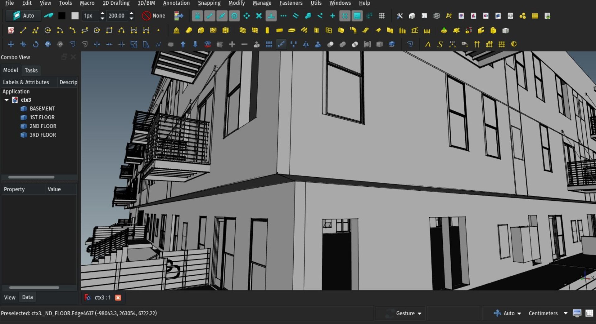
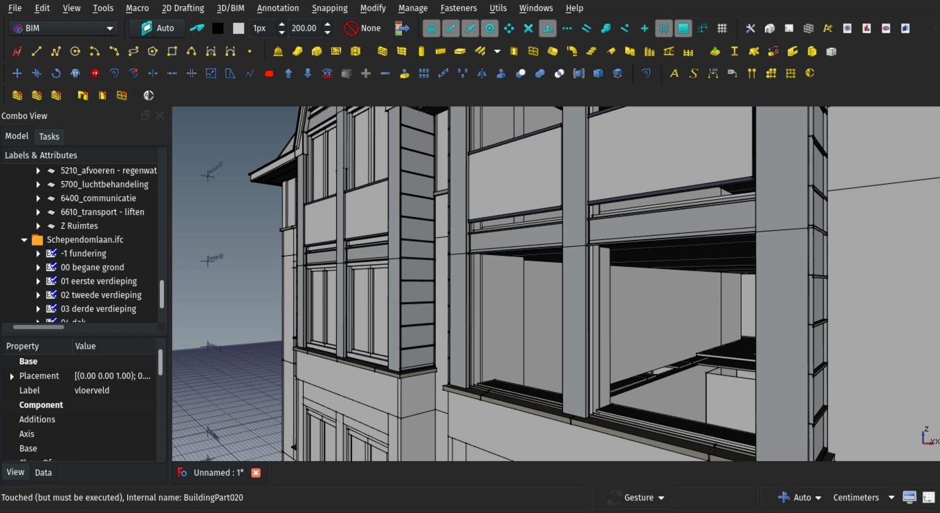
Most IFC files you'll find around have a full IfcProject -> IfcSite -> IfcBuilding -> IfcBuildingStorey structure, even though this is not specifically required by the IFC specifications (the only thing really mandatory is one IfcProject and at least one building component, being building or storey). But it has become a kind of general habit to always have all the four in each and every IFC file.
There is of course a kind of logic there, that you cannot have a storey without a building around it, and there is always a site under any built building...
In practice, however, you don't always know or care about these when starting a BIM project. In FreeCAD, more than often, when importing an IFC file, the first thing I do is delete the project, site and building, as they usually only serve to contain a storey, which in FreeCAD is a Building Part and can live on its own, as it does not necessarily represent a storey.
So now there is an import option that you can turn on, to skip importing the project and site, and also building and storey if there is only one of each, and place all the imported contents in to a group.
This makes it easy to handle partial IFC files, that only contain parts of a building, not an entire one. For example, the structural or MEP part of a building. You can have your main FreeCAD model, and import the contents of partial IFC file, each into a separate group. When you need to update one specific file, it is just a matter of deleting the group and re-import the file.
This paves the way for a bit more automatic behaviour similar to the Reference tool, where new versions of the IFC file could automatically be detected, the user notified, and a one-click update performed.
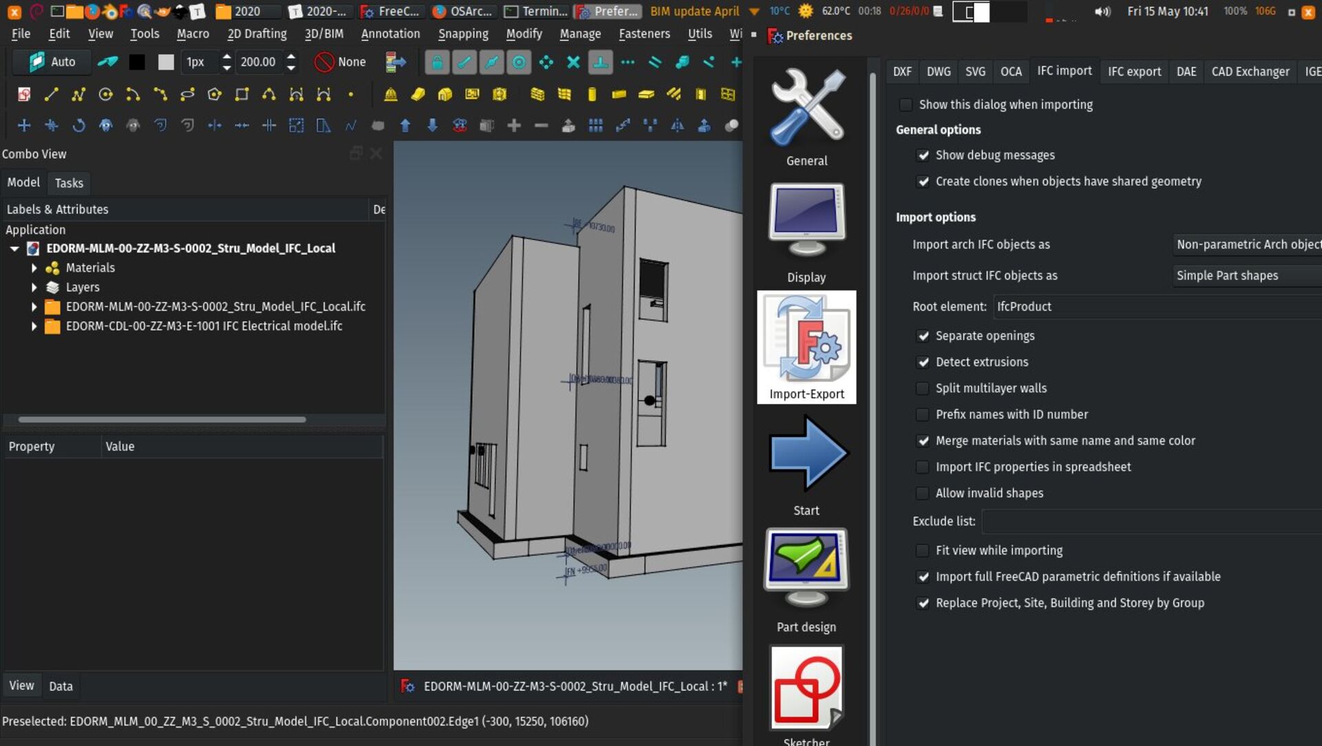
Annotation style editor
This is preliminary work to support annotation styles in Draft. These are styles defined by the user, where you can configure things like text font, size, colour or dimension arrows, and have these styles applied to any of your texts, dimensions or labels. On changing any setting of the style, all objects that use it change automatically.
We started by implementing an editor and a system to store the styles in the document. Next steps will be adapting the different annotation objects to support the styles.
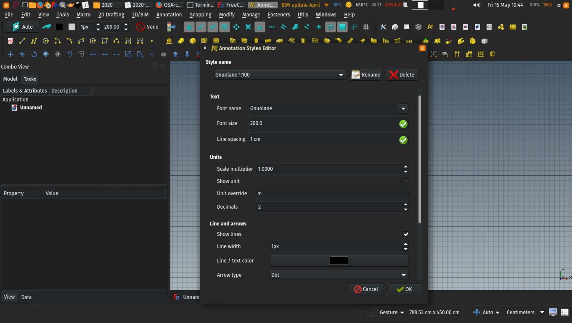
Truss tool
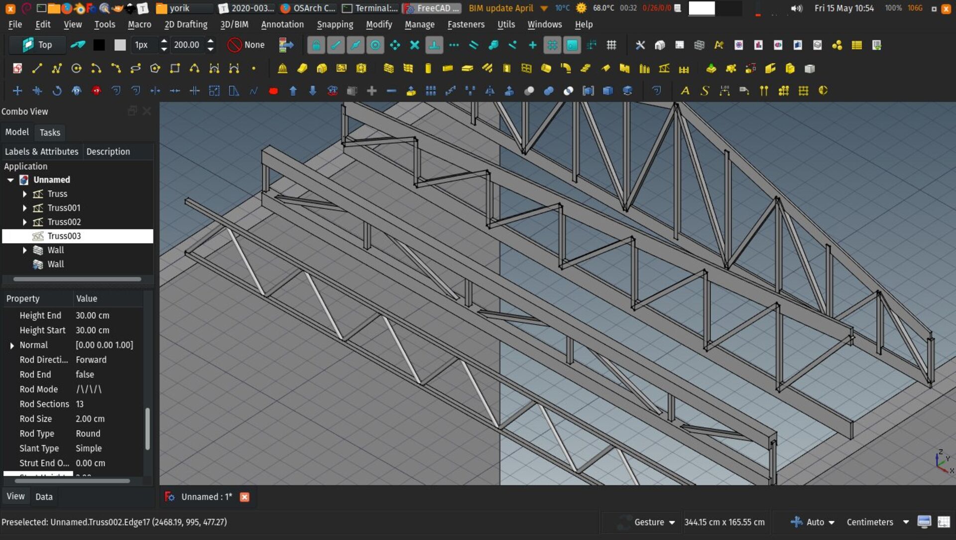
A new Truss tool has landed in Arch and BIM workbenches. This tool allow you to build a variety of trusses. Like walls or beams, they are constructed from a baseline, and different properties define the shape of the truss, its height, the way supporting and intermediary members are drawn, etc.
It also supports multi-materials, so you can assign a different material to the inferior and superior members and the intermediary members.
As there is no proper IFC class for trusses, they are currently exported as IfcBeams. Suggestions are welcome to better this point, though.
Open-source IFC-based classification
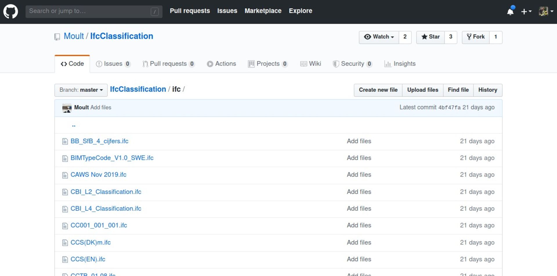
Dion Moult, the author of BlenderBIM (and quite some work in FreeCAD itself), has published a series of building classification systems such as OmniClass or Uniformat in IFC format. FreeCAD can now use these IFC files with the BIM Classification tool.
Both the former XML-based format and this IFC format can be used by the tool, the advantage of IFC being that it doesn't depend on vendors since it is managed the open-source way, and it can be fixed/bettered by users.
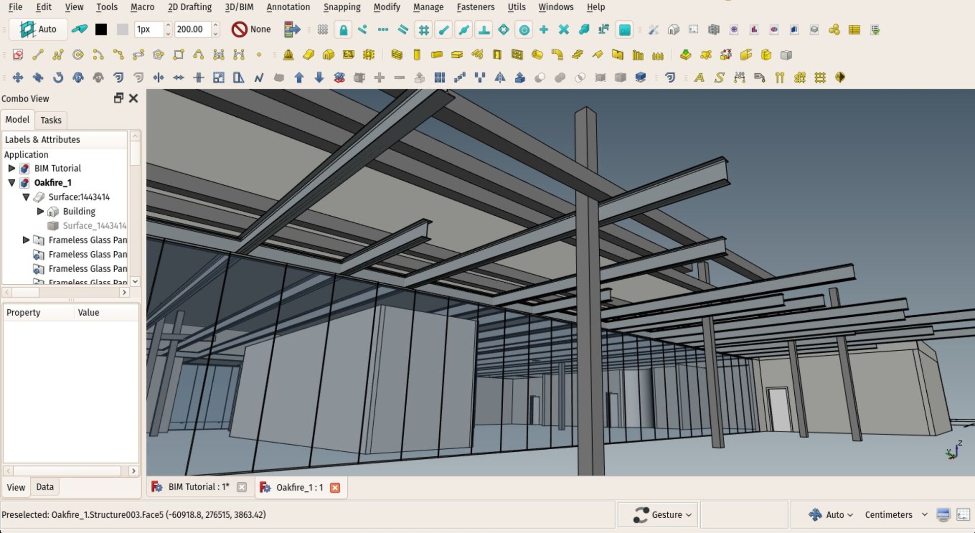
Curtain wall tool
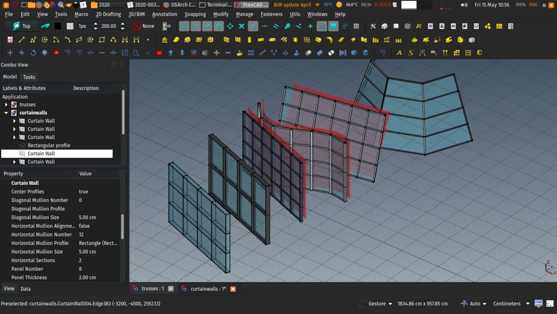
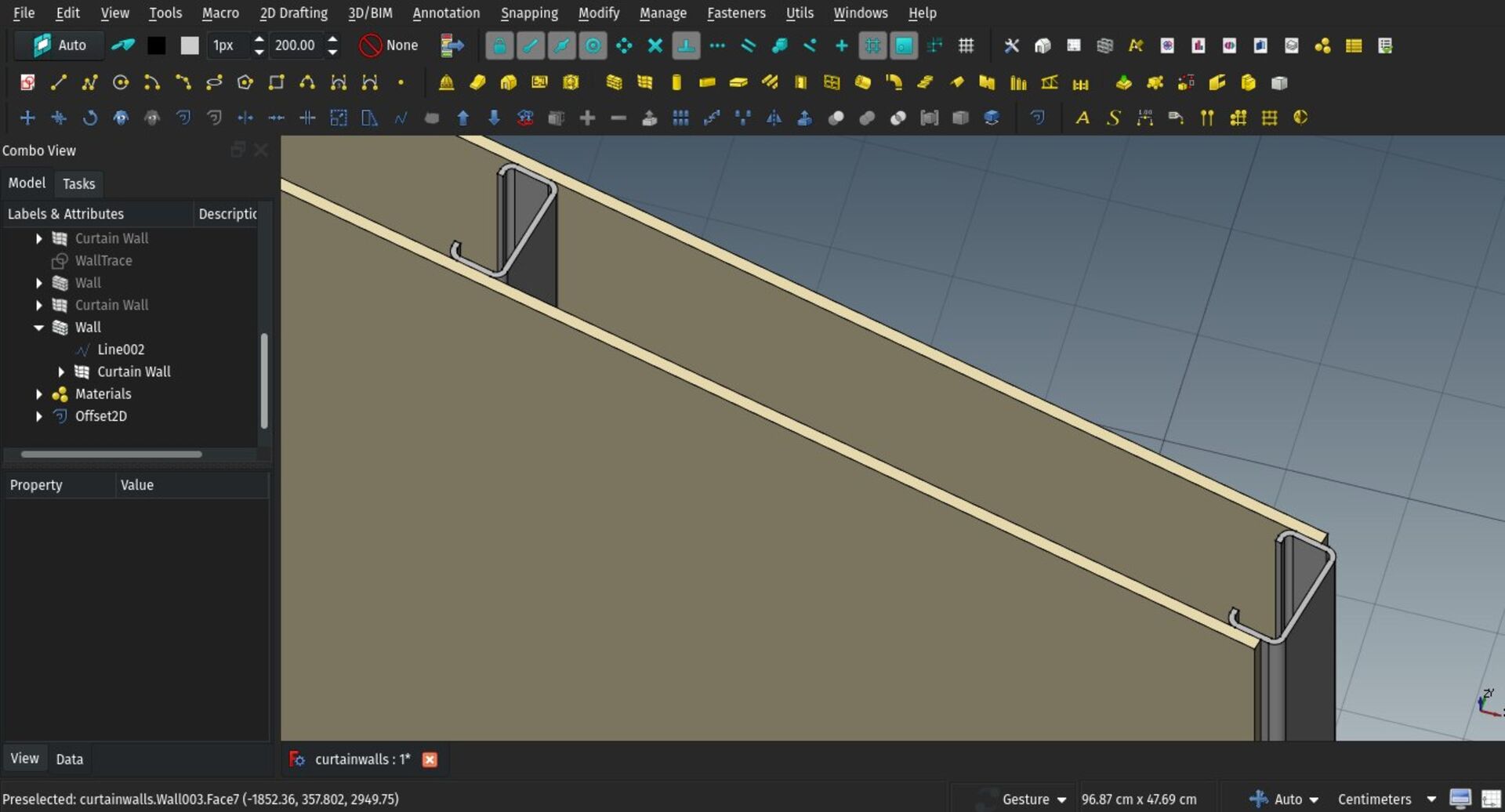
A new Curtain wall tool has been also added to Arch and BIM workbenches. This is still preliminary work, since curtain walls is a complex and delicate matter, but I believe the base is pretty solid.
The curtain wall object needs a base surface to work on. If none is selected when using the tool, you can simply draw a line between two points, like the standard wall tool. The surface is then subdivided into rows and columns, and four points extracted from the surface subdivisions, forming quadrangular facets. Each facet receives a panel, the horizontal lines receive horizontal mullions, and the vertical lines vertical mullions. If the 4 points are not co-planar, two triangles are formed instead of a quad, and a diagonal mullion is added.
This covers basically almost any kind of base surface, no matter how complex. To get quadrangular facets, however, the base face must be ruled. A ruled surface is basically a surface formed by sweeping a straight line along guides. Straight extrusions or portions of cones are ruled surfaces. But surfaces formed by four NURBS curves might not be. The tool will work on any of them, but produce triangles in the latter case. This, however, is the only way it could be built in real-life anyway...
You can achieve more complex subdivisions that the regular ones proposed by the tool, by preparing and subdividing your base surface yourself before using the tool, for example by subtracting perpendicular faces from it, to produce custom subdivisions, and setting horizontal and vertical subdivisions properties of the curtain wall to 1, to not subdivide any further.
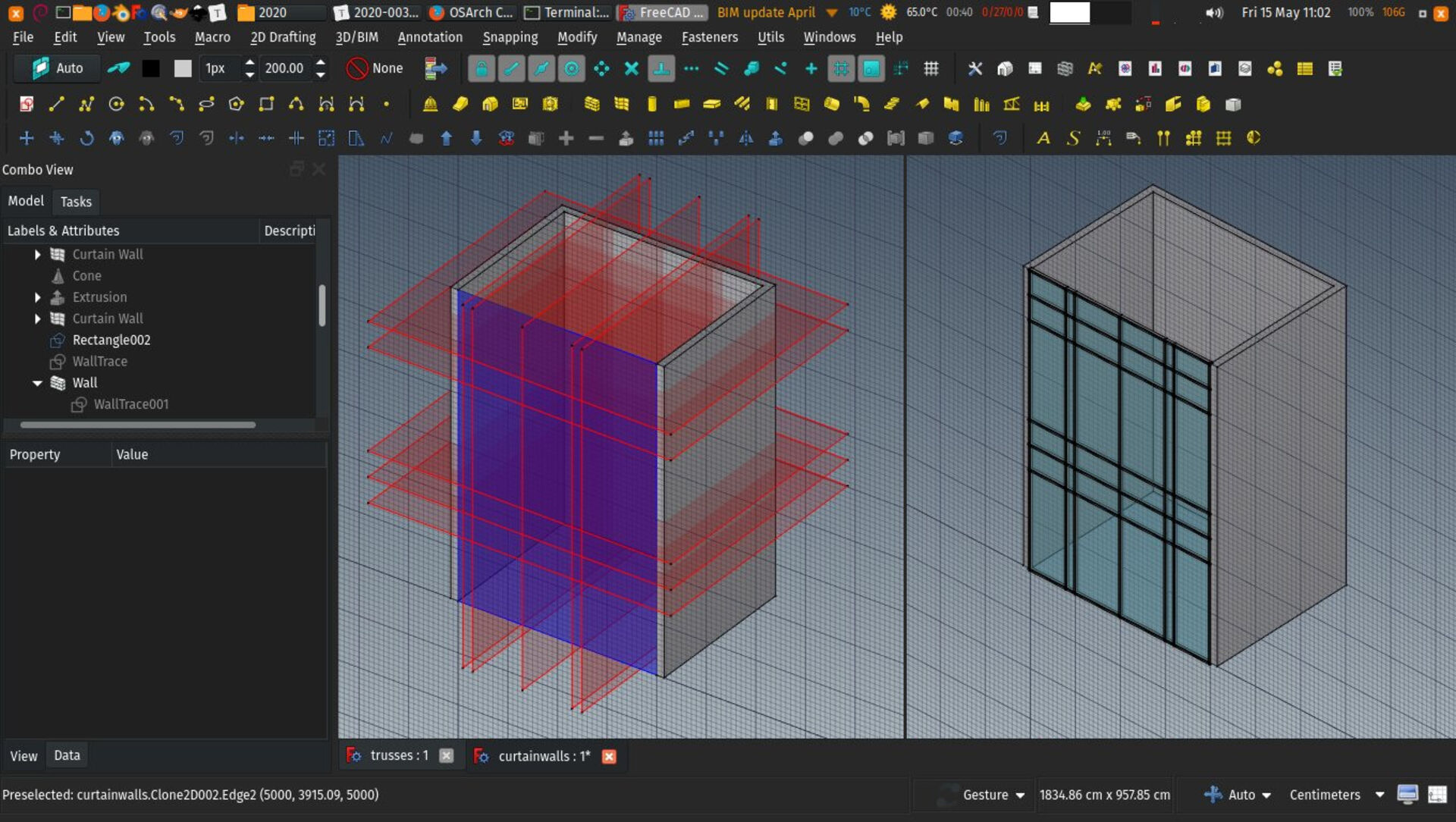
As mostly everywhere in FreeCAD, it's pretty easy to keep all this nicely parametric, using a base rectangle (Draft or Sketch) with controllable dimensions, and using expressions to set the positions of the intermediary planes accordingly, for example using an array where the number of vertical divisions depends on the height of the base rectangle.
Shapefiles importer
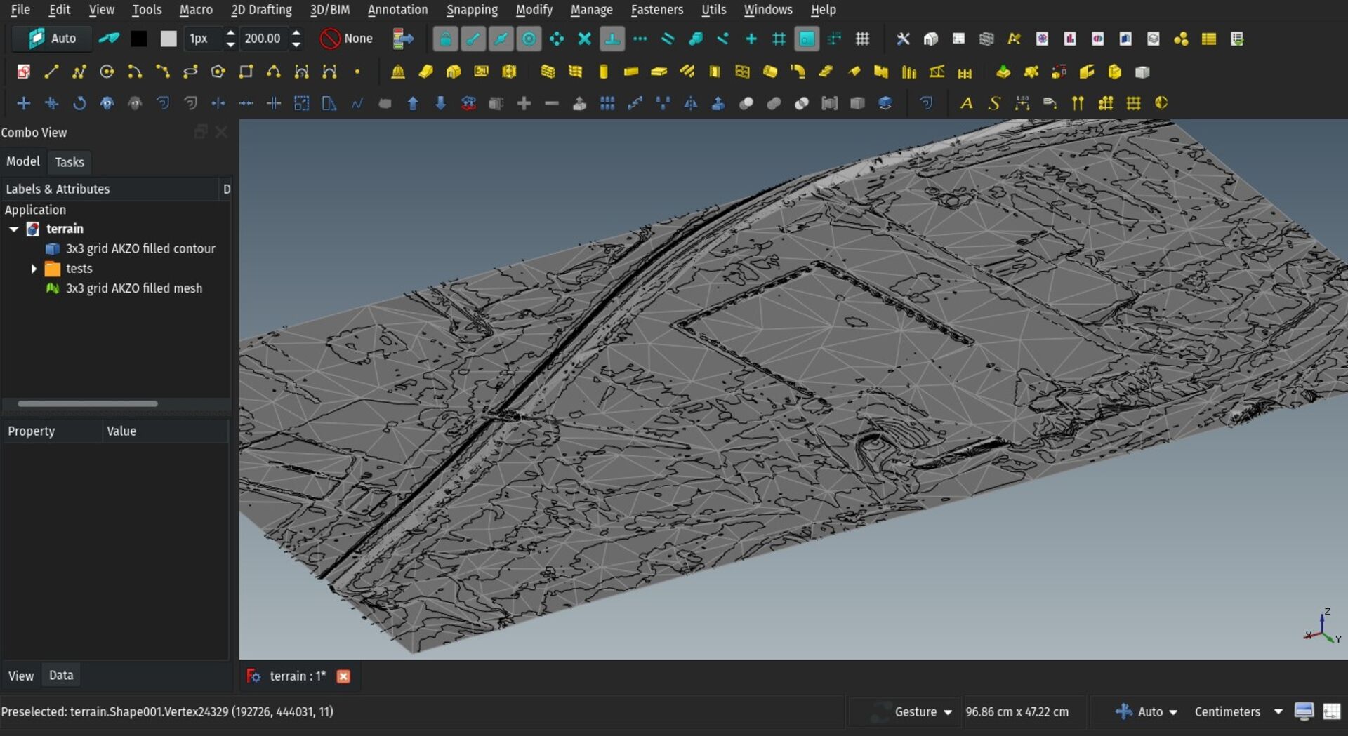
Shapefiles are the main file format for GIS. They are actually composed of 3 files, a .shp, .shx and .dbf file). One contains the geometry, one the fields related to the geometry, and one the projection system information.
Shapefiles contain 2D points, polylines or polygons, referenced to a specific geographic projection system. They can also contain fields, which can be numbers or text. Each shape (point, polyline, polygon) can have an own value in each of the fields. This is the great gem of GIS, the ability to tie geometric objects to information cells stored in an attached database. You can do anything with these, such as tag each object (for example to give names to streets), or give a certain ID to points.
Another very common use of fields is to give an elevation to each shape of the shapefile. This can be used by FreeCAD when you import the file to draw each shape at its correct elevation.
At the moment, the importer will not perform any transformation of the coordinates system from the file, and will place each shape at the location stored in the file. Geographic projection coordinates is a vast subject currently out of my understanding, but I'd like to be able to do some simple transformations, such as import in meters or place the imported file at the 3D space origin. Help welcome!
IFC Roundtripping
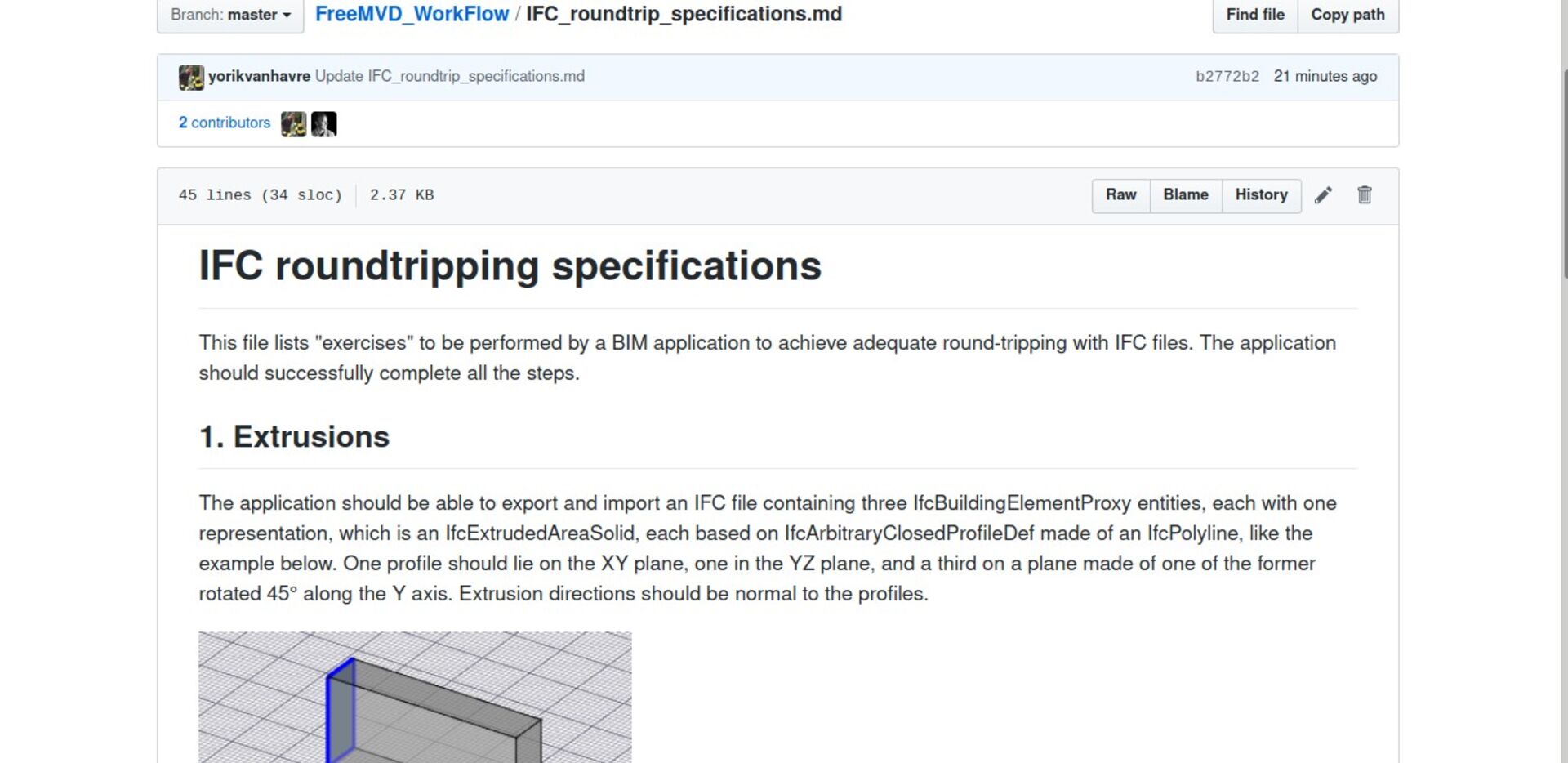
Roundtripping basically consists in exporting your model from any BIM application to IFC, re-importing the IFC file into the same application, and being able to continue working without having lost any significant information. during the operation.
Of course, IFC is a complex format, and it does not have the exact the same set of features of your favourite BIM application (FreeCAD, of course ). So the IFC file never reflects exactly your model in its original BIM application. So you will inevitably loose some information on the way. The question here is to be able to identify and save what you actually need.
Some will tell you IFC is not made for that purpose and we should abandon that idea. However, me and several others think IFC has all the capabilities for and could be used that way. Ryan Schultz and I have a long history of trying to address such IFC translation issues between FreeCAD and Revit.
Now with osarch folks we are starting to build step-by-step simple examples of what works and where, hopefully we can progress a bit in isolating the really important information and have better understanding of what works on each BIM platform (and of course solve problems on FOSS ones and make them the best IFC platforms out there!)
That's it for this month, thanks for reading, and see you next month!
FreeCAD BIM development news - April 2020
Hi all!
Here goes a new update about the development of BIM tools for FreeCAD. I'll try my best to resume posting here once a month and hopefully do some videos again next time.
We have some great stuff to share this month, and it's great to see a momentum picking, with new developers putting some efforts into Arch/BIM development. This is visible not only in FreeCAD, but in other BIM FOSS projects as well. Have a look at the very cool osarch.org if you haven't yet.
Thanks a million to everybody who supports me on Patreon or Liberapay! This real makes a nice difference for me as I can throw a nice amount of time into FreeCAD development.
So here is what I've been working with this month:
Better partial IFC handling
Most IFC files you'll find around have a full IfcProject -> IfcSite -> IfcBuilding -> IfcBuildingStorey structure, even though this is not specifically required by the IFC specifications (the only thing really mandatory is one IfcProject and at least one building component, being building or storey). But it has become a kind of general habit to always have all the four in each and every IFC file.
There is of course a kind of logic there, that you cannot have a storey without a building around it, and there is always a site under any built building...
In practice, however, you don't always know or care about these when starting a BIM project. In FreeCAD, more than often, when importing an IFC file, the first thing I do is delete the project, site and building, as they usually only serve to contain a storey, which in FreeCAD is a Building Part and can live on its own, as it does not necessarily represent a storey.
So now there is an import option that you can turn on, to skip importing the project and site, and also building and storey if there is only one of each, and place all the imported contents in to a group.
This makes it easy to handle partial IFC files, that only contain parts of a building, not an entire one. For example, the structural or MEP part of a building. You can have your main FreeCAD model, and import the contents of partial IFC file, each into a separate group. When you need to update one specific file, it is just a matter of deleting the group and re-import the file.
This paves the way for a bit more automatic behaviour similar to the Reference tool, where new versions of the IFC file could automatically be detected, the user notified, and a one-click update performed.
Annotation style editor
This is preliminary work to support annotation styles in Draft. These are styles defined by the user, where you can configure things like text font, size, colour or dimension arrows, and have these styles applied to any of your texts, dimensions or labels. On changing any setting of the style, all objects that use it change automatically.
We started by implementing an editor and a system to store the styles in the document. Next steps will be adapting the different annotation objects to support the styles.
Truss tool
A new Truss tool has landed in Arch and BIM workbenches. This tool allow you to build a variety of trusses. Like walls or beams, they are constructed from a baseline, and different properties define the shape of the truss, its height, the way supporting and intermediary members are drawn, etc.
It also supports multi-materials, so you can assign a different material to the inferior and superior members and the intermediary members.
As there is no proper IFC class for trusses, they are currently exported as IfcBeams. Suggestions are welcome to better this point, though.
Open-source IFC-based classification
Dion Moult, the author of BlenderBIM (and quite some work in FreeCAD itself), has published a series of building classification systems such as OmniClass or Uniformat in IFC format. FreeCAD can now use these IFC files with the BIM Classification tool.
Both the former XML-based format and this IFC format can be used by the tool, the advantage of IFC being that it doesn't depend on vendors since it is managed the open-source way, and it can be fixed/bettered by users.
Curtain wall tool
A new Curtain wall tool has been also added to Arch and BIM workbenches. This is still preliminary work, since curtain walls is a complex and delicate matter, but I believe the base is pretty solid.
The curtain wall object needs a base surface to work on. If none is selected when using the tool, you can simply draw a line between two points, like the standard wall tool. The surface is then subdivided into rows and columns, and four points extracted from the surface subdivisions, forming quadrangular facets. Each facet receives a panel, the horizontal lines receive horizontal mullions, and the vertical lines vertical mullions. If the 4 points are not co-planar, two triangles are formed instead of a quad, and a diagonal mullion is added.
This covers basically almost any kind of base surface, no matter how complex. To get quadrangular facets, however, the base face must be ruled. A ruled surface is basically a surface formed by sweeping a straight line along guides. Straight extrusions or portions of cones are ruled surfaces. But surfaces formed by four NURBS curves might not be. The tool will work on any of them, but produce triangles in the latter case. This, however, is the only way it could be built in real-life anyway...
You can achieve more complex subdivisions that the regular ones proposed by the tool, by preparing and subdividing your base surface yourself before using the tool, for example by subtracting perpendicular faces from it, to produce custom subdivisions, and setting horizontal and vertical subdivisions properties of the curtain wall to 1, to not subdivide any further.
As mostly everywhere in FreeCAD, it's pretty easy to keep all this nicely parametric, using a base rectangle (Draft or Sketch) with controllable dimensions, and using expressions to set the positions of the intermediary planes accordingly, for example using an array where the number of vertical divisions depends on the height of the base rectangle.
Shapefiles importer
Shapefiles are the main file format for GIS. They are actually composed of 3 files, a .shp, .shx and .dbf file). One contains the geometry, one the fields related to the geometry, and one the projection system information.
Shapefiles contain 2D points, polylines or polygons, referenced to a specific geographic projection system. They can also contain fields, which can be numbers or text. Each shape (point, polyline, polygon) can have an own value in each of the fields. This is the great gem of GIS, the ability to tie geometric objects to information cells stored in an attached database. You can do anything with these, such as tag each object (for example to give names to streets), or give a certain ID to points.
Another very common use of fields is to give an elevation to each shape of the shapefile. This can be used by FreeCAD when you import the file to draw each shape at its correct elevation.
At the moment, the importer will not perform any transformation of the coordinates system from the file, and will place each shape at the location stored in the file. Geographic projection coordinates is a vast subject currently out of my understanding, but I'd like to be able to do some simple transformations, such as import in meters or place the imported file at the 3D space origin. Help welcome!
IFC Roundtripping
Roundtripping basically consists in exporting your model from any BIM application to IFC, re-importing the IFC file into the same application, and being able to continue working without having lost any significant information. during the operation.
Of course, IFC is a complex format, and it does not have the exact the same set of features of your favourite BIM application (FreeCAD, of course
Some will tell you IFC is not made for that purpose and we should abandon that idea. However, me and several others think IFC has all the capabilities for and could be used that way. Ryan Schultz and I have a long history of trying to address such IFC translation issues between FreeCAD and Revit.
Now with osarch folks we are starting to build step-by-step simple examples of what works and where, hopefully we can progress a bit in isolating the really important information and have better understanding of what works on each BIM platform (and of course solve problems on FOSS ones and make them the best IFC platforms out there!)
That's it for this month, thanks for reading, and see you next month!

Re: BIM/Arch development news articles from Yorik's blog
At work we usually make an assembly for each truss object from all the single truss members. This assembly gets the Ifc type what it is, usually a beam, but could be a column or even a slab too.
truss column:
- index.jpeg (9.32 KiB) Viewed 4315 times
truss beam:
- beam.png (74.81 KiB) Viewed 4315 times
space framework (in German Raumfachwerk) for wide span slabs:
- raumfachwerk.jpg (78.19 KiB) Viewed 4315 times
Re: BIM/Arch development news articles from Yorik's blog
Hmm that's an interesting approach... The "host" object could be a shapeless IfcBeam, IfcColumn or whatever, and have a series if IfcMembers underneath
Re: BIM/Arch development news articles from Yorik's blog
exactly an assembly and the assembly is IfcBeam or what the truss is. Similar to the multilayered wall we have seen here https://forum.freecadweb.org/viewtopic. ... 93#p399642
I may post some example ifc created by allplan in this regard.
I may post some example ifc created by allplan in this regard.
FreeCAD BIM development news - May 2020
Cross-posting from https://yorik.uncreated.net/blog/2020-008-freecad-may
Hi everybody!
This is our monthly development log for the BIM tools for FreeCAD. This month again we have quite some cool stuff to show, and we now have Carlo Pavan on board as new BIM developer! Some of his experiments are already available for testing, see below!
As always, thanks to everybody who contributes to my Patreon or Liberapay campaigns!
Curtain wall improvements: frame walls
The Curtain wall tool we introduced last month has received a couple of tweaks so it can now be used to make the framing of frame walls. Frame walls are those lightweight walls where the structure is not made of a uniform, filling material such as brick or concrete, but a light supporting frame made of metal or wood studs, on which panels (wood or gypsum, usually) are fixed on both sides. The inner spacing between the studs is sometimes filled with insulation material.
Now, you can build a curtain wall from the same baseline as a normal wall, and make it construct only vertical mullions, and no panels. By combining this and a standard wall with a void space inside, you can build a perfect frame wall. The procedure is explained in detail in the Curtain wall documentation.
With the method above, the "host" wall is kept independent from the framing, so it is easy to turn them on or off independently, which is good for large models.
This all still needs a bit more polish, the ability to create everything in one go, better display switching between different wall representations (with framing, with wall layers, etc), but I think the structure is there already and quite solid and flexible.
Draft grid border
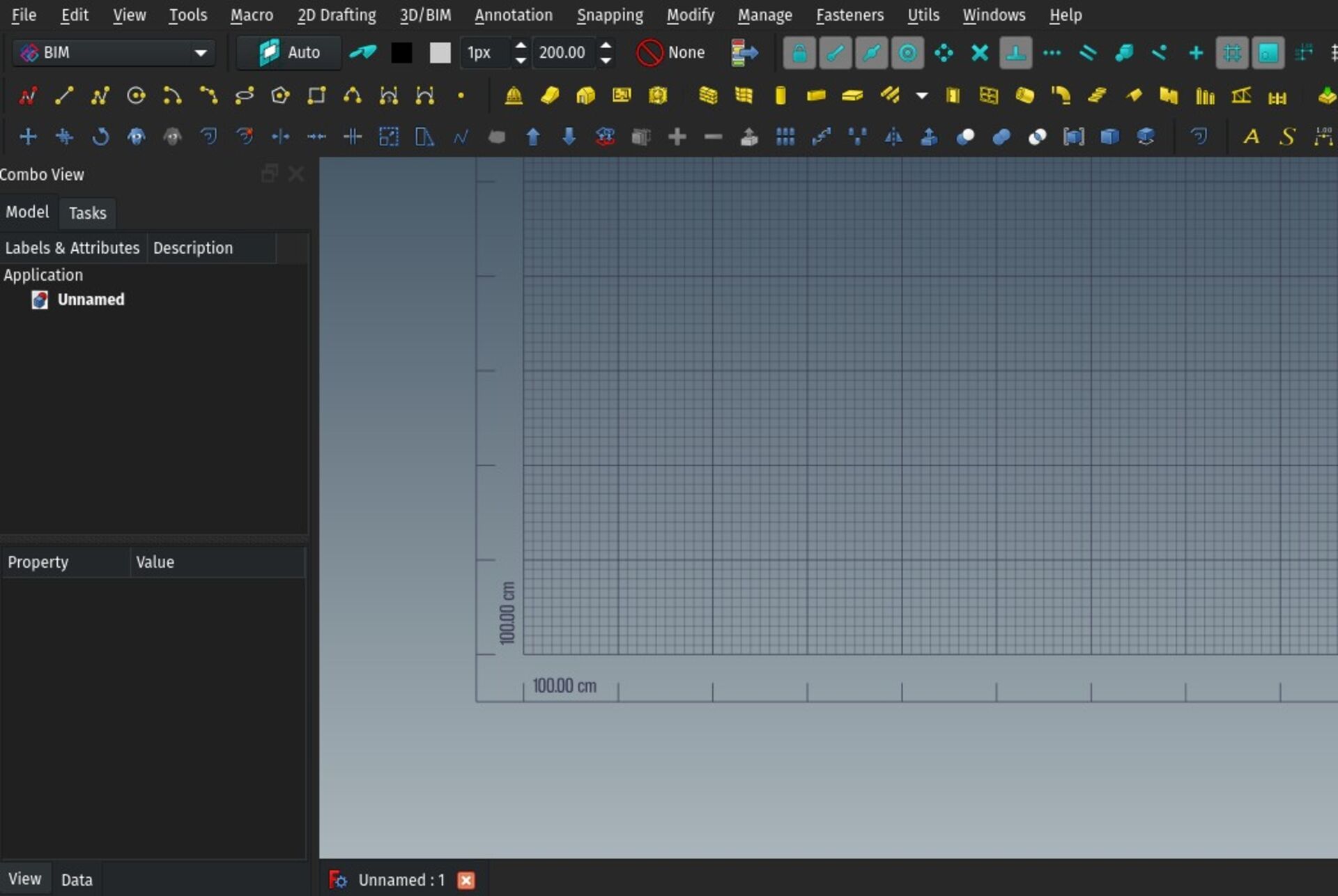
The Draft grid, which represents the current working plane, has received a bit of styling, it now has an additional border and shows the size of a large grid square in the corner.
Not the most important update of course, but it always feels good to have a bit of additional blink in one's work space... I'm wondering if other useful things could not be added there... A standing human figure, maybe?
Install IfcOpenShell automatically
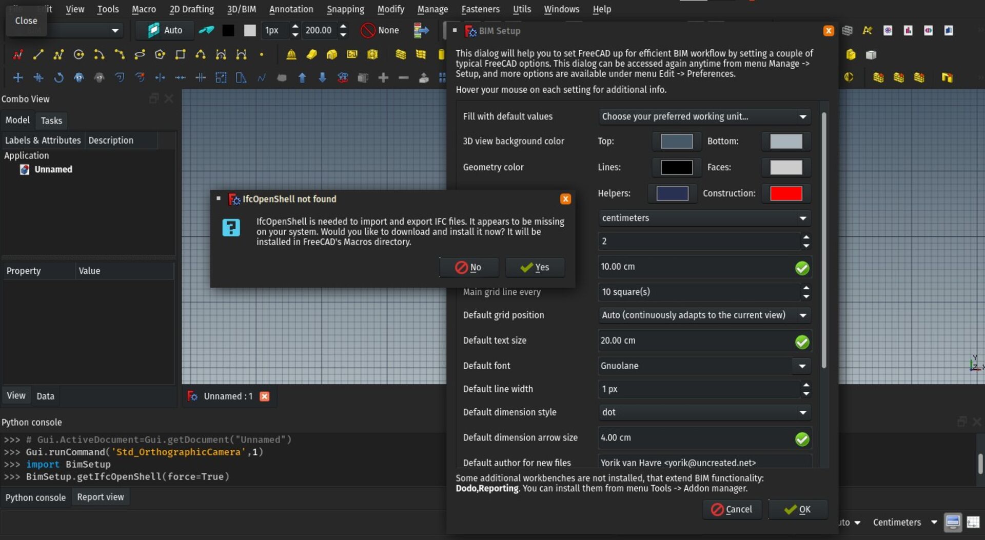
IfcOpenShell is the main component responsible for IFC import/export in FreeCAD. It is now also used extensively in BlenderBIM too. Up to now, we have been shipping IfcOpenShell with the install package of FreeCAD, but some users, specially on Ubuntu, still struggle with finding an appropriate version of IfcOpenShell.
Now, when entering the setup screen of the BIM workbench, if IfcOpenShell is not installed on your system, you will be offered to download and install it automatically. It will be installed in the Macros folder of FreeCAD, so it won't disturb anything on your system.
You can still install IfcOpenShell manually as well.
Rhino 3dm import
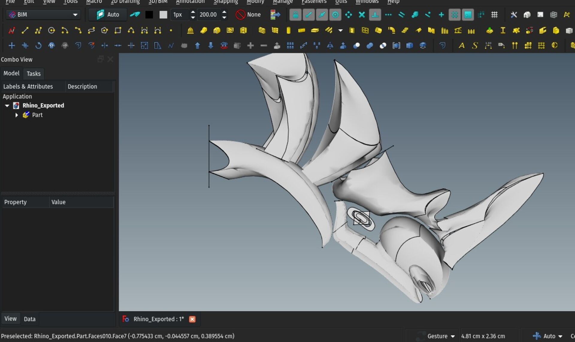
Rhinoceros is a popular 3D modelling platform. It is very similar to FreeCAD, and I like it a lot. Although it is proprietary, its developers make a lot of efforts to play the game nicely: It is far less expensive than other similar tools, and they publish many components as open-source, as, for example, the openNURBS library, a component that allows other applications to read and write Rhino's native 3DM file format.
So far, openNURBS was only available as a C++ library, but it is since some time available as a Python module too via pip. Keith Sloan has packaged it under a FreeCAD addon named ImportNURBS which you can install via the FreeCAD addons manager.
If you have Rhino files, come and help us test!
Carlo Pavan's experimental wall and opening tools
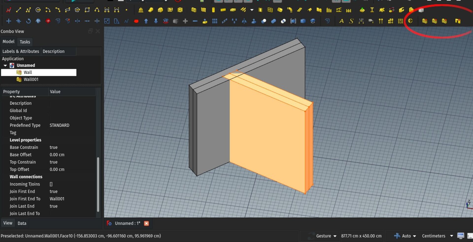
Welcome one more BIM developer in FreeCAD! Carlo has started experimenting with new concepts, mostly based on recent FreeCAD developments such as Realthunder's App Link functionality. This slowly introduces more PartDesign-like workflow to BIM.
Basically we have two new experimental tools, already available in the BIM workbench (you need to run it with a recent FreeCAD 0.19 to test). A wall tool and a window/door/opening tool (Existing wall and window tools are still there, and will be kept at least until the new ones would replace them perfectly, in fact I'm thinking of integrating both together at some point).
The wall tool has the main advantage over the existing one to support automatic joining. Each wall holds a list of other walls it needs to connect to, and it always "knows" its central axis line, which is used to calculate intersection angles. However, much is still not supported, such as layers or IFC export.
The opening/window tool makes use of App Links, which allows a much better handling of complex windows made of several subcomponents. You can design a very complex window with other workbenches, make an App Part, elect that as a window type, and have inserted windows behave as simple, lightweight copies of the type object. This also works with local coordinate systems.
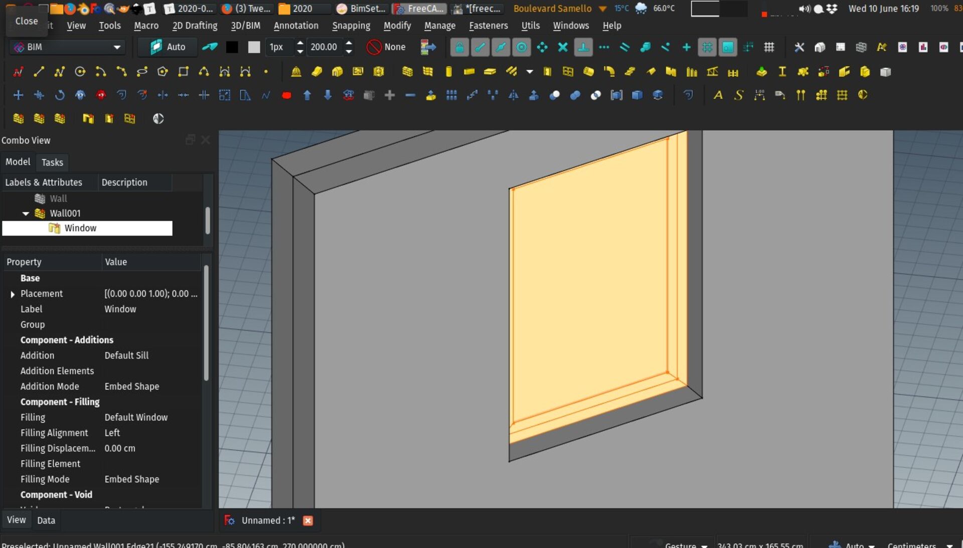
Here too many features of the original window tool are not yet there, but I'm really excited by the experiment. Have a try!
Facebinder improvements
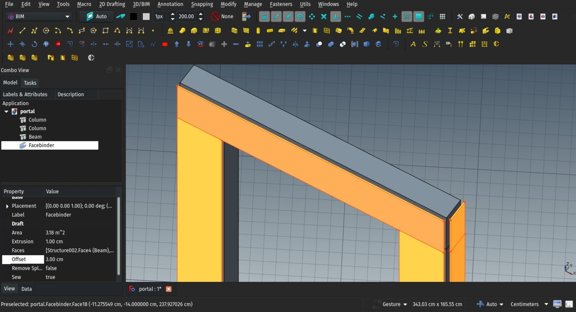
The Facebinder tool is a handy little feature that allows you to pick up faces from different objects and create a new object from that, that can also be extruded. I added two new properties to the Facebinder object: **Offset**, that allows you to give a spacing distance between the original faces and the facebinder object, and **Area** which shows the total area prior to extrusion.
Ladybug integration
This is for me the most exciting news from this report. Ladybug is a set of tools (of which ladybug is only one of the components), that provide climate and environment analysis tools to BIM projects, in order to help you to design better environment-integrated projects. It has tools to analyze climate data (ladybug), to produce analyses with energy-analysis software (honeybee), fluid/winds simulations (butterfly) and more.
The ladybug tools are fully open-source, but so far they have been mostly used in proprietary environments and visual programming systems such as Revit's Dynamo or Rhino's Grasshopper.
However, being programmed fully in Python and having an excellent API, they are very easy to use in FreeCAD as well. I started with ladybug itself (I documented my explorations here if you are interested), but the plan is of course to go further and integrate the whole suite. So far what works:
* If Ladybug is found on your system (it is easy to install via pip), it is used instead of the pysolar library to generate solar diagrams for your Site objects. There is no visible difference between both, but it will in the future reduce dependency on other libraries.
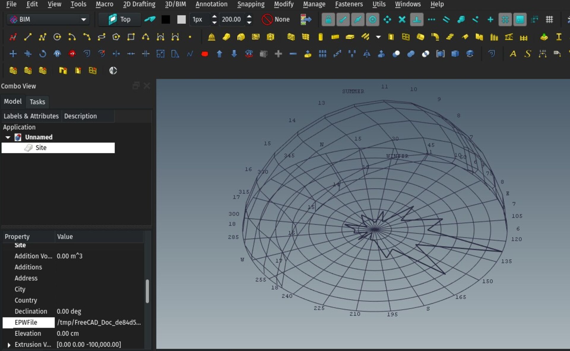
* Site objects gained an **EPW file** property, which you can load with an EPW file corresponding to your region. EPW files contain climate data such as wind directions and temperatures for a whole year, for a given location.
* If an EPW file is loaded, the Site object can display, aside from the solar diagram, a **wind rose diagram**.
Next developments on the roadmap are generating series of shadows studies for different times of the year, and start implementing honeybee.
Having a strong and well-maintained open-source environmental tools suite such as ladybug is really a blessing for BIM development, I don't know why we didn't start this sooner!
Profile command
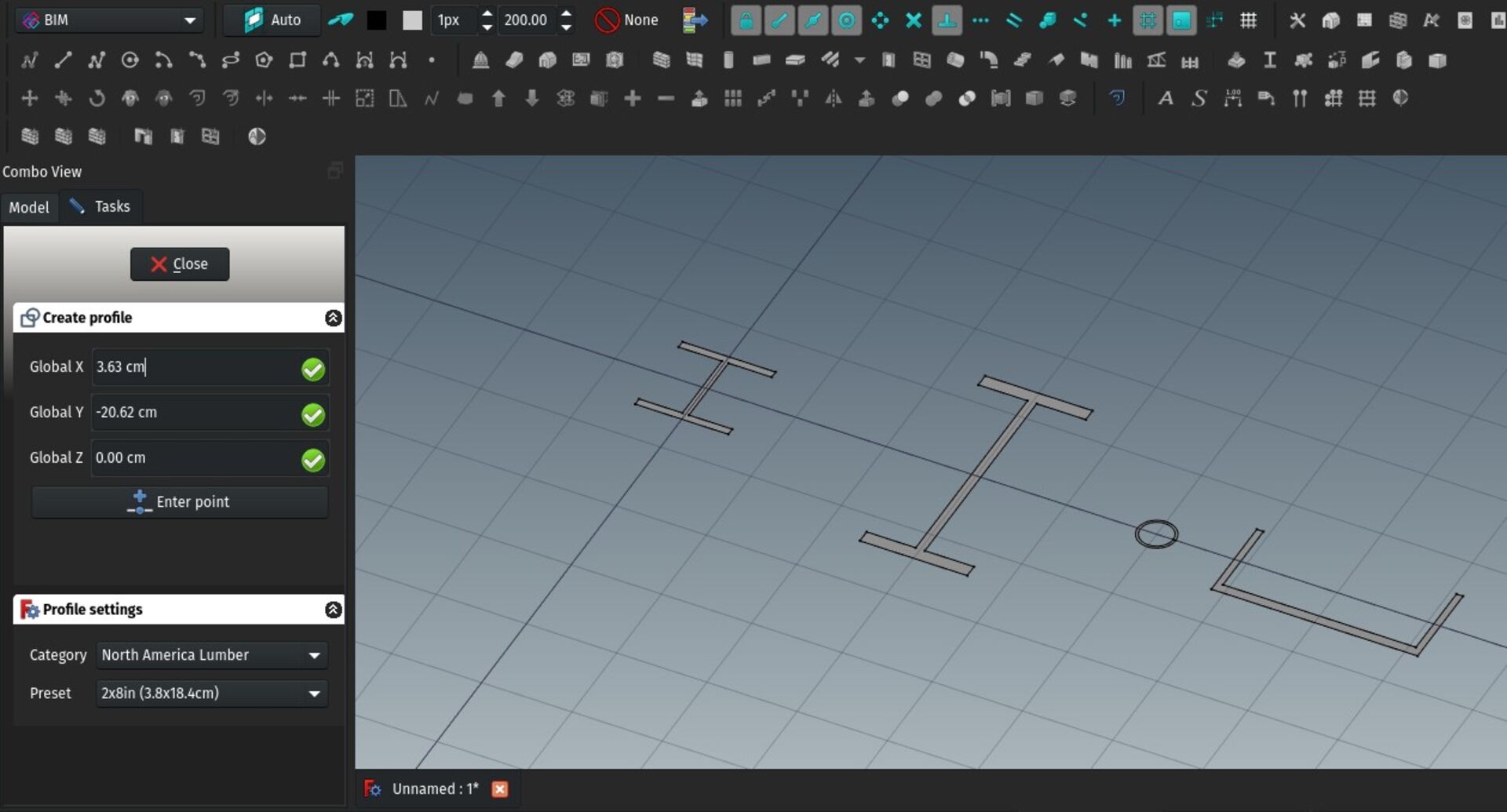
Structure tools in FreeCAD did already allow to choose a profile from a list of presets. But so far it was not possible to create these parametric profiles alone, outside of the Structure tools. Now a new Profile tool was added, which allows you to do just that. So these parametric profiles can now be used with other tools as well (an obvious candidate is of course the curtain wall tool).
The profile tool contains already a big list of presets of standard metallic and wooden profiles, and you are able to add your own custom list as an additional CSV file too. If you know some categories of profiles that you think might be good to add, why not contribute
IFC support for rectangle/circle based profiles
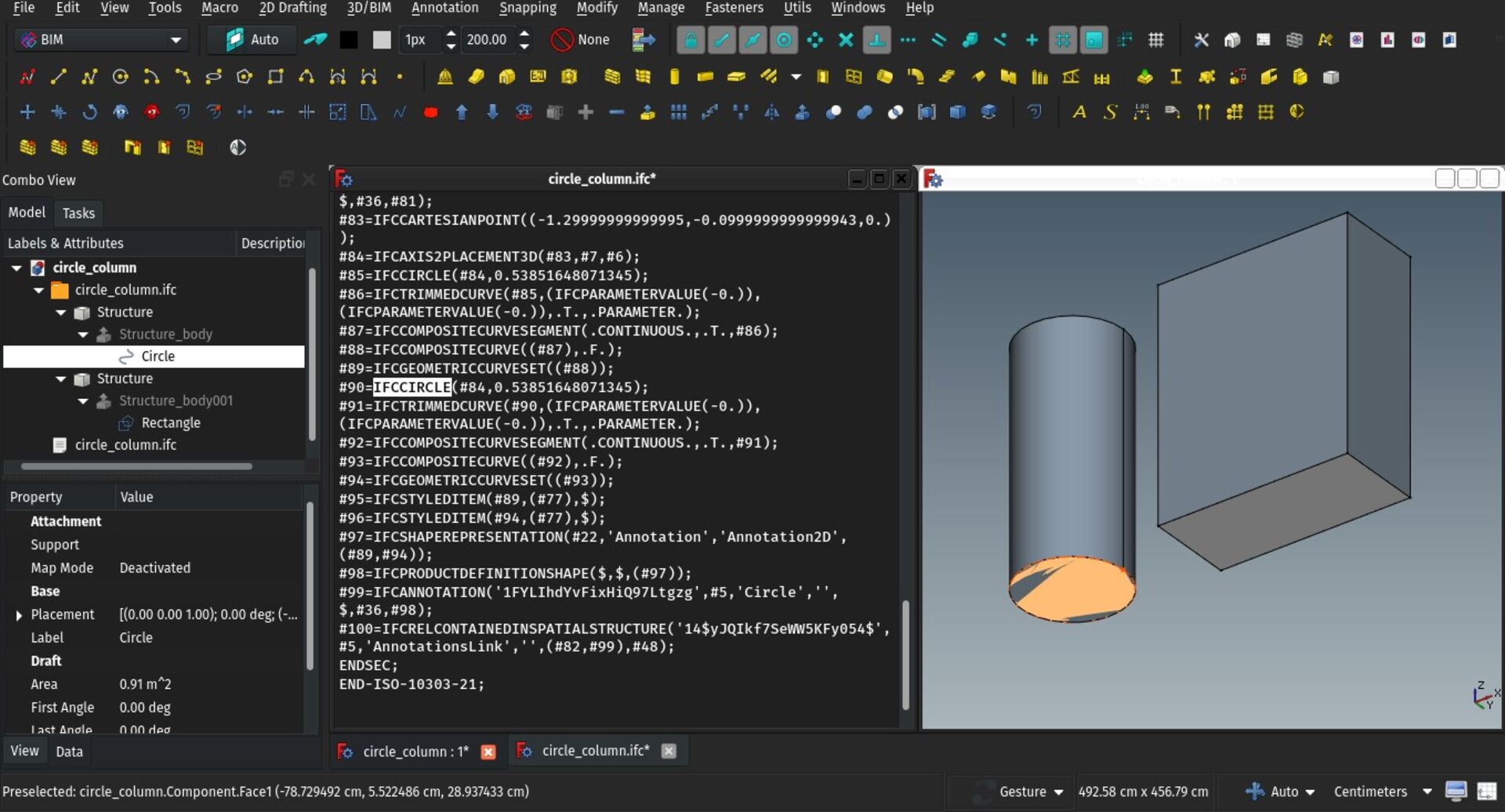
Following up the roundtrip experiments we've been doing with Ryan and others at osarch, I've added a couple of improvements to the IFC importer and exporter of FreeCAD. Aside from bugfixes, it now correctly imports and exports and recognizes rectangle- and circle-based profiles, which were previously exported and reimported as simple polylines or non-parametric curves.
These small adjustments really don't weight much in the general handling of IFC files, but they bit by bit turn the use of IFC files sounder in a project development workflow, as they better the editability of objects, and turn the whole file more parametric.
That's it for this month I guess, stay tuned for more next month!
Cheers
Yorik
Hi everybody!
This is our monthly development log for the BIM tools for FreeCAD. This month again we have quite some cool stuff to show, and we now have Carlo Pavan on board as new BIM developer! Some of his experiments are already available for testing, see below!
As always, thanks to everybody who contributes to my Patreon or Liberapay campaigns!
Curtain wall improvements: frame walls
The Curtain wall tool we introduced last month has received a couple of tweaks so it can now be used to make the framing of frame walls. Frame walls are those lightweight walls where the structure is not made of a uniform, filling material such as brick or concrete, but a light supporting frame made of metal or wood studs, on which panels (wood or gypsum, usually) are fixed on both sides. The inner spacing between the studs is sometimes filled with insulation material.
Now, you can build a curtain wall from the same baseline as a normal wall, and make it construct only vertical mullions, and no panels. By combining this and a standard wall with a void space inside, you can build a perfect frame wall. The procedure is explained in detail in the Curtain wall documentation.
With the method above, the "host" wall is kept independent from the framing, so it is easy to turn them on or off independently, which is good for large models.
This all still needs a bit more polish, the ability to create everything in one go, better display switching between different wall representations (with framing, with wall layers, etc), but I think the structure is there already and quite solid and flexible.
Draft grid border
The Draft grid, which represents the current working plane, has received a bit of styling, it now has an additional border and shows the size of a large grid square in the corner.
Not the most important update of course, but it always feels good to have a bit of additional blink in one's work space... I'm wondering if other useful things could not be added there... A standing human figure, maybe?
Install IfcOpenShell automatically
IfcOpenShell is the main component responsible for IFC import/export in FreeCAD. It is now also used extensively in BlenderBIM too. Up to now, we have been shipping IfcOpenShell with the install package of FreeCAD, but some users, specially on Ubuntu, still struggle with finding an appropriate version of IfcOpenShell.
Now, when entering the setup screen of the BIM workbench, if IfcOpenShell is not installed on your system, you will be offered to download and install it automatically. It will be installed in the Macros folder of FreeCAD, so it won't disturb anything on your system.
You can still install IfcOpenShell manually as well.
Rhino 3dm import
Rhinoceros is a popular 3D modelling platform. It is very similar to FreeCAD, and I like it a lot. Although it is proprietary, its developers make a lot of efforts to play the game nicely: It is far less expensive than other similar tools, and they publish many components as open-source, as, for example, the openNURBS library, a component that allows other applications to read and write Rhino's native 3DM file format.
So far, openNURBS was only available as a C++ library, but it is since some time available as a Python module too via pip. Keith Sloan has packaged it under a FreeCAD addon named ImportNURBS which you can install via the FreeCAD addons manager.
If you have Rhino files, come and help us test!
Carlo Pavan's experimental wall and opening tools
Welcome one more BIM developer in FreeCAD! Carlo has started experimenting with new concepts, mostly based on recent FreeCAD developments such as Realthunder's App Link functionality. This slowly introduces more PartDesign-like workflow to BIM.
Basically we have two new experimental tools, already available in the BIM workbench (you need to run it with a recent FreeCAD 0.19 to test). A wall tool and a window/door/opening tool (Existing wall and window tools are still there, and will be kept at least until the new ones would replace them perfectly, in fact I'm thinking of integrating both together at some point).
The wall tool has the main advantage over the existing one to support automatic joining. Each wall holds a list of other walls it needs to connect to, and it always "knows" its central axis line, which is used to calculate intersection angles. However, much is still not supported, such as layers or IFC export.
The opening/window tool makes use of App Links, which allows a much better handling of complex windows made of several subcomponents. You can design a very complex window with other workbenches, make an App Part, elect that as a window type, and have inserted windows behave as simple, lightweight copies of the type object. This also works with local coordinate systems.
Here too many features of the original window tool are not yet there, but I'm really excited by the experiment. Have a try!
Facebinder improvements
The Facebinder tool is a handy little feature that allows you to pick up faces from different objects and create a new object from that, that can also be extruded. I added two new properties to the Facebinder object: **Offset**, that allows you to give a spacing distance between the original faces and the facebinder object, and **Area** which shows the total area prior to extrusion.
Ladybug integration
This is for me the most exciting news from this report. Ladybug is a set of tools (of which ladybug is only one of the components), that provide climate and environment analysis tools to BIM projects, in order to help you to design better environment-integrated projects. It has tools to analyze climate data (ladybug), to produce analyses with energy-analysis software (honeybee), fluid/winds simulations (butterfly) and more.
The ladybug tools are fully open-source, but so far they have been mostly used in proprietary environments and visual programming systems such as Revit's Dynamo or Rhino's Grasshopper.
However, being programmed fully in Python and having an excellent API, they are very easy to use in FreeCAD as well. I started with ladybug itself (I documented my explorations here if you are interested), but the plan is of course to go further and integrate the whole suite. So far what works:
* If Ladybug is found on your system (it is easy to install via pip), it is used instead of the pysolar library to generate solar diagrams for your Site objects. There is no visible difference between both, but it will in the future reduce dependency on other libraries.
* Site objects gained an **EPW file** property, which you can load with an EPW file corresponding to your region. EPW files contain climate data such as wind directions and temperatures for a whole year, for a given location.
* If an EPW file is loaded, the Site object can display, aside from the solar diagram, a **wind rose diagram**.
Next developments on the roadmap are generating series of shadows studies for different times of the year, and start implementing honeybee.
Having a strong and well-maintained open-source environmental tools suite such as ladybug is really a blessing for BIM development, I don't know why we didn't start this sooner!
Profile command
Structure tools in FreeCAD did already allow to choose a profile from a list of presets. But so far it was not possible to create these parametric profiles alone, outside of the Structure tools. Now a new Profile tool was added, which allows you to do just that. So these parametric profiles can now be used with other tools as well (an obvious candidate is of course the curtain wall tool).
The profile tool contains already a big list of presets of standard metallic and wooden profiles, and you are able to add your own custom list as an additional CSV file too. If you know some categories of profiles that you think might be good to add, why not contribute
IFC support for rectangle/circle based profiles
Following up the roundtrip experiments we've been doing with Ryan and others at osarch, I've added a couple of improvements to the IFC importer and exporter of FreeCAD. Aside from bugfixes, it now correctly imports and exports and recognizes rectangle- and circle-based profiles, which were previously exported and reimported as simple polylines or non-parametric curves.
These small adjustments really don't weight much in the general handling of IFC files, but they bit by bit turn the use of IFC files sounder in a project development workflow, as they better the editability of objects, and turn the whole file more parametric.
That's it for this month I guess, stay tuned for more next month!
Cheers
Yorik