First Try with FreeCAD and a Sketch based Architectural Workflow

A forum dedicated to the Draft, Arch and BIM workbenches development.
Forum rules
Be nice to others! Respect the FreeCAD code of conduct!
Post Reply
User avatar
JQL
Posts: 35
Joined: Thu Oct 29, 2020 11:52 am

First Try with FreeCAD and a Sketch based Architectural Workflow

Post by JQL »

I've recently played with FreeCAD, using sketches for an Architectural workflow. The concept is incredible and I was much impressed with how easy it was to create geometric constrains with FreeCAD. I saw great potential on the workflow but then I also failed drastically with it.

I noticed that if I generated building's geometry from the sketches and at a later time added other geometry to the base sketches the whole building model would break.

I finally gave up and got back to using my usual modelling software, but was a bit sad and I'm trying to investigate if there are better ways of doing what I was trying to do with FreeCAD. If I find a solution to my issues, I could regard FreeCAD as a solid alternative to any other CAD/BIM software I know of.

Can any of you provide help concerning this? Have you found ways of using sketches that dynamically change your models without breaking?

I have my FreeCAD and system info at the end, as well as the model I've been playing with.

Here's the example I tried the workflow with and an generic step by step description of the process and what went wrong with it:

Image

Image

Image

My approach to sketches was what I imagined was the most intuitive for a Sketch based architectural workflow. After understanding about the topological naming I have to think on how to adapt it or if I would need to follow a different workflow or how much intuitive would that be for me.

I will share the progress I make on that investigation from time to time, hoping that might also help others.

1 - BASE SKETCH

So, what I did at first was to draw every base line of my building's geometry in floor plan. Like a true first sketch you'd hand draw, but with precise geometry and using a dimension based constrain system. The way I saw it at first was that this was very similar to the Sketches an architect starts with, but instead of loose and vague, it would be accurate and parametric. A natural second step after a paper sketch... I had seen the light! :)

2 - SECONDARY SKETCHES

My initial idea was to pick sketch lines to create walls from and hit the wall button, then pick the slab lines and hit the slab button, and so on. Then FreeCAD would parametrically generate elements based on those lines and whichever chages were made to them.

I soon realized that I couldn't pick individual lines/curves/polylines from the base sketch. So, in order to base my individual building elements, I started building secondary sketches that were connected to the base Sketch. That worked very well by usign the "edge linked to external geometry" tool in the sketcher workbench and picking elements from the Base Sketch as external geometry.

I made a new sketch for each arch element I needed and sometimes I reused the same sketch. That seemed an almost ideal workflow.

Here's a gif of that process:

Image

I understand now that this was where problems stemed from.

Q1: Should we avoid this method altogether?

Q2: If I would use the "four sketch lines that form a wire" method could I safely connect new sketches to that "wire sketch geometry"?

3 - BREAKING SKETCHES

The truth is that as as long as no new geometry would be added to the base sketch this method was working really nicelly. I kept adding new sketches on top of the base sketch, connected to it, and changing base sketch dimensions, angles or constrains was smoothly changing walls and slabs.

However I then tried going back to base Sketch and added an extra wall. This broke every other sketch. Not understanding why that happened, I simply redid the secondary sketches only to have them break again later.

Here's a gif showing what happened:

Image

And another gif where I undo and redo the sketch lines to better show the effects on every secondary Sketch:

Image

4 - MULTIPLE WALLS BASED ON A SINGLE SKETCH

Two of the secondary sketches in this example were baselines for walls. I noticed that if I had all walls in the same sketch sometimes the wall tool didn't generate them. It happened consistently if walls were mixing closed loops with open lines (though right now I can't consistently reproduce it).

So I started splitting my wall sketches into wall types. In this case having a sketch for exterior wall and another for interior walls worked. It resulted into two models, one was a continuous wall, for the exterior, the other was a group of several wall elements. Everything seemed fine in FreeCAD however, exporting the file to IFC and opening it on Blender only showed 2 walls. The exterior continuous wall, and a single interior wall element from the multiwall group. Here is an image:

Image

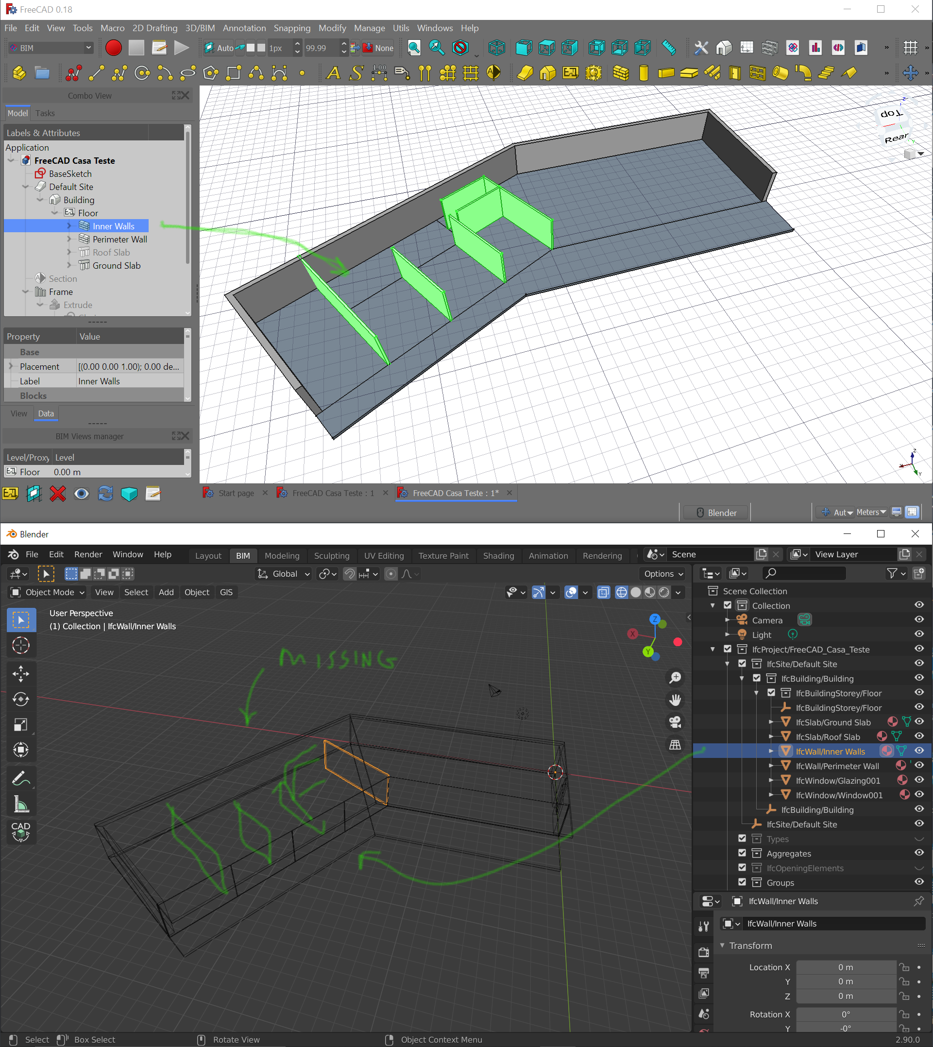
I imagine that IFC doesn't like to have wall geometries that are not continuous and that might be the problem I have there.

However, I'm not thinking that I will be creating an independent base sketch for each wall and honestly the method I used is very convenient as it consistently keeps regenerating walls as changes happen in the base sketch geometry (as you can see in several of the posted gifs).

Of course, introducing a change to the base Sketch that would break the model, would break these walls.

Q3: I wonder if there is an easy method to generate walls, that is similar to the one I used, but doesn't break and at the same time is exportable to IFC?

Q4: Is this an issue from my method that works geometrically within FreeCAD but is bad practice in IFC and should be avoided or is it a bug in Blender's IFC implementation?

5 - ISSUES WITH WINDOWS/DOORS

Finally I was also investigating on windows and glazing when this happened and I had some issues with them too where I couldn't exactly find the best workflow. Here are some of the issues I had with them:
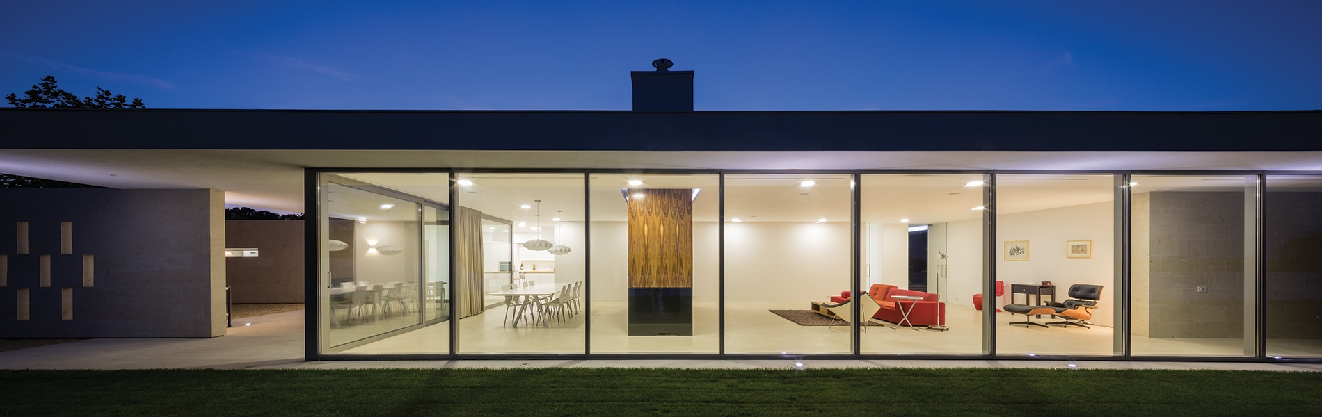
  • I couldn't find how to design a façade like the following image and place it on a Sketch base line, splitting the line into N panels. My idea was that when the base Sketch changed the windows would be evenly distributed throughout the line:
Q5: What would be the best method for that, that wouldn't envolve having to copy paste a window component manually?
Image
  • At the same time, placing windows in a wall and reference their position to the bas.e sketch wasn't straightforward either (I will investigate the method @paullee is using and maybe find some answers there)
  • I understood that I should change window measurements in the properties panel but I didn't find a nice way to visually change their geometry or relate it with other sketches. That would be key for making the windows align/relate with changing geometry or to visually model them in a wysiwyg approach that I rather work with.
  • I understood that it wasn't very easy to configure window types. They had a base sketch that was a bit hard to understand how it worked and change it, and I understood that they had predefined settings that would have to be defined from start in an initial dialog, but after placing them I couldn't find how to cycle through the options.
  • It would be great to have a way to customize or create our own settings and window types.
  • I also understood that windows were not connected to walls. They had an absolute position in space and so, when a wall changed position, the window would stay put, floating in midair:
Image

Q6: Is it straightforward to create windows and/or façades (windows+walls or windows+structures) based on vertical sketches and have those sketches based on floor plan sketches, instead of inserting windows manually into walls?

I think the most important issues and questions I faced are layed out here. I just tried following what I imagined could be an intuitive approach using the small info I could find about FreeCAD and Sketches and this is a result of a trial and error process that ended up in a dead end for me. I would really appreciate some guidance going forward from here but I hope I'm not pushing my luck, or asking too many questions and making too many bad assumptions as to how and if the software works as it should.

Here is the model I used for my test:
FreeCAD Casa Teste.FCStd
(57.78 KiB) Downloaded 83 times
And FreeCAD's about info:

OS: Windows 10
Word size of OS: 64-bit
Word size of FreeCAD: 64-bit
Version: 0.18.4 (GitTag)
Build type: Release
Branch: releases/FreeCAD-0-18
Hash: 980bf9060e28555fecd9e3462f68ca74007b70f8
Python version: 3.6.6
Qt version: 5.6.2
Coin version: 4.0.0a
OCC version: 7.3.0
Locale: Portuguese/Portugal (pt_PT)

Thanks in advance,

João
Last edited by JQL on Mon Nov 02, 2020 12:15 pm, edited 1 time in total.
chrisb
Veteran
Posts: 54201
Joined: Tue Mar 17, 2015 9:14 am

Re: First Try with FreeCAD and a Sketch based Architectural Workflow

Post by chrisb »

Hi and welcome to the forum!

I'm not very familiar with Arch, so I can't go into the details. Your model breaks due to the well known and severe topological naming problem. Have a look at this page, especially the paragraph about creating stable models.

There is already improvement implemented, but this will - most probably - not come in 0.19 into master.
A Sketcher Lecture with in-depth information is available in English, auf Deutsch, en français, en español.
User avatar
JQL
Posts: 35
Joined: Thu Oct 29, 2020 11:52 am

Re: First Try with FreeCAD and a Sketch based Architectural Workflow

Post by JQL »

Hi Chris and thanks for your input. I was reading the info you pointed me to and it seems toponaming is an issue of geometry and also sketches.

I can imagine using datum planes to things like floors but in architecture as you might know there should be vertical alignments between elements. Therefore it does make sense to have a base sketch that is providing the global geometric rules for the whole building. Is there any way of forming base sketches like a grid, where you add and remove lines or geometry to the grid without breaking it? The thing is that for a building it's usually this base grid that becomes the basis for that vertical alignment. Also by grid I don't mean that it has to be an orthogonal grid, but it is a base geometry rule for the whole construction.

The thing is that rooms are not a result of the division of an external shell nor the shell is a result of adding rooms next to each other. Architectural design stems from the interaction of both. So, in this sense, it's a bit different from part design or object design as we are not handling solids but structures or skeletons.

Would skeleton like sketches work?

A second question I had is related to façades. I was imagining a vertical sketch would be an ideal method to design a façade. Datum planes concept could also be used for this as if they are vertical they can represent the projection of the façade on the plane. However facades of the building follow the angles of it's plan's perimeter and this is always changing, stretching, rotating and adapting. They aren't always aligned with X or Y (not always vertical but let's disregard that for now). Is it possible to have a datum plane that is aligned with a sketch line from the base sketch and if that line changes it's angle, the datum plane changes the angle to match?

An image to illustrate:
Datum plane.jpg
Datum plane.jpg (121.67 KiB) Viewed 2570 times
Last edited by JQL on Fri Oct 30, 2020 10:38 am, edited 1 time in total.
chrisb
Veteran
Posts: 54201
Joined: Tue Mar 17, 2015 9:14 am

Re: First Try with FreeCAD and a Sketch based Architectural Workflow

Post by chrisb »

If you add or delete elements to the master sketch things depending on it can break. To keep it stable you can add additional sketches without such issues.

No idea with your second question, but the image is not visible. Upload it directly to the forum.
A Sketcher Lecture with in-depth information is available in English, auf Deutsch, en français, en español.
User avatar
bitacovir
Veteran
Posts: 1570
Joined: Sat Apr 19, 2014 6:23 am
Contact:

Re: First Try with FreeCAD and a Sketch based Architectural Workflow

Post by bitacovir »

I recommend you to work with FC 0.19

Sketcher was not created for architecture workflow. There are very few cases for analysis. Any exploration is to discover how far the technology can be used for that purpose. If you do find a complete way, good. You open a new field of use. If you don't, good. You can document it and someone later could refine the technology and implement new features for that purpose.

Some facts that I see in the sketches of your file that broke:
You cannot delete lines or vertexes in the BaseSketch, because InnerWall and Slab sketch will lost references.
You cannot draw new lines on previous vertexes in BaseSketch, because InnerWall and Slab sketch will lost references.

You need to find a workaround for BaseSketch edition using the restriction system that already is implemented. And maybe this method only will work for some cases, not all of them.
What about if you don't delete lines in BaseSketch. If you need a new configuration, just add more lines.
Try not to draw lines on previous vertexes in BaseSketch, but rather locate the lines near these vertexes with a restriction by dimension of 1mm.
I tried this method, adding some new lines and it helped in some way:
FreeCAD Casa TesteRMC.FCStd
(10.36 KiB) Downloaded 50 times
IJy9WOoPuq (2).gif
IJy9WOoPuq (2).gif (904 KiB) Viewed 2703 times
PD: there is a manual for sketcher in the forum. You should study it.
::bitacovir::
==================
One must be absolutely modern.
Arthur Rimbaud (A Season in Hell -1873)

Canal Youtube Grupo Telegram de FreeCAD Español

My personal web site
My GitHub repository
Mini Airflow Tunnel Project
User avatar
saso
Veteran
Posts: 1924
Joined: Fri May 16, 2014 1:14 pm
Contact:

Re: First Try with FreeCAD and a Sketch based Architectural Workflow

Post by saso »

Try if realthunders version will make your model stable, he made an implementation that tries to solve the toponaming issue... There are also Sketcher Exports that might also be useful for your workflow.

Make a copy of your file and just open it in his version of FC, right at the beginning it will ask you if you want to recompute the model, it will add the needed logic to it that help to manage this topological relations and then just try to do the same changes that break your model and report back :)

https://github.com/realthunder/FreeCAD_ ... s/tag/0.11
Last edited by saso on Thu Oct 29, 2020 10:57 pm, edited 1 time in total.
paullee
Veteran
Posts: 5118
Joined: Wed May 04, 2016 3:58 pm

Re: First Try with FreeCAD and a Sketch based Architectural Workflow

Post by paullee »

JQL wrote: Thu Oct 29, 2020 8:23 pm Ping
Welcome ! Maybe later some findings / recommendation can be cross-posted back to OSArch to get more attention.

One thing each time.

I have a glance at the Sketch and would have some findings, trying to revise it.

In the meantime -
  1. You choose to use Sketch to do a complex layout, as I do :)
  2. It is a seemingly more complicated and challenging way but could be more powerful so more issues as I had found, so good luck :lol:
  3. Check the wikii, Chrisb's manual etc. on Sketch, you will find Shortcut e.g. 'c' for Coincident constraint, 'n' for Perpendicular, and best practice in constraints to help doing Sketch
  4. As Bitacovir suggests, you may try download the latest 0.19_pre, which is needed e.g. for the Villa Savoye model, to get latest features
    (I have saved a nos. of development version of Appimage for Linux, so if I have the latest one has some problem, I use the last one which just works)
paullee
Veteran
Posts: 5118
Joined: Wed May 04, 2016 3:58 pm

Re: First Try with FreeCAD and a Sketch based Architectural Workflow

Post by paullee »

First thing about Sketch
  1. As indicated last time, Avoid having more than 2 lines coincident on 1 points
  2. There are a few cases and I revise that - I have not delete your original edge atm to minimise disruption to dependent sketch
  3. Usually I would try to build an ArchWall based on the Master / Base Sketch and see anything strange to see if better to do something on the Sketch
  4. Check Sketch wiki, Chrisb's tutorial about Sketch particular Constraints
  5. E.g. you can point an edge's End Point and another Edge and add Perpendicular Constraints
    (I.e. no need to do 2 constraints - 1 Point on Edge Constraints + Perpendicular Constraints)
  6. As you 'select' to do a Complex Sketch as layout (this is tricky and require more thinking :lol: ), think, by try and error, how to do the Dimensional constraints - to ease subsequent editing
    (E.g. Villa Savoye model, may have 2 dimensional constraints on the overall square layout, then internal wall set out from 1 or 2 of the external wall - this way, whatever the change in internal layout, the overall dimension is not changed - if that is the governing thing)
FreeCAD Casa Teste.FCStd_ paul_ r1.FCStd
(79.22 KiB) Downloaded 68 times
Screenshot from 2020-10-30 07-57-46.png
Screenshot from 2020-10-30 07-57-46.png (261.22 KiB) Viewed 2639 times
Screenshot from 2020-10-30 07-59-53.png
Screenshot from 2020-10-30 07-59-53.png (266.9 KiB) Viewed 2639 times
Screenshot from 2020-10-30 08-07-01.png
Screenshot from 2020-10-30 08-07-01.png (256.3 KiB) Viewed 2639 times
Screenshot from 2020-10-30 08-07-28.png
Screenshot from 2020-10-30 08-07-28.png (302.27 KiB) Viewed 2639 times
User avatar
JQL
Posts: 35
Joined: Thu Oct 29, 2020 11:52 am

Re: First Try with FreeCAD and a Sketch based Architectural Workflow

Post by JQL »

First of all, thanks everyone for your continued input. It's been very helpful, promissing and enlightening.
chrisb wrote: Thu Oct 29, 2020 9:28 pm No idea with your second question, but the image is not visible. Upload it directly to the forum.
Hi Chris and thanks again for your feedback. I'm understanding better about breaking sketches circumstances. I've updated the image link. It's representing a vertical datum plane, for basing a sketch, but the plane is based on another sketch line. The base sketch is an horizontal floor plan geometry. If that sketch changes and that line moves, rotates, stretches, would it be possible to have the vertical Datum plane following it?

If this wouldn't be possible with datum planes, how would I do it?

@bitacovir,

Thanks for your input. I will keep trying possible architectural workflows with sketches in my free time. I hope I get something going as I really like the possibilities. Hopefully I will report here and make questions along the way and those might lead somewhere useful, as you say.

I thought the suggestion of adding Sketches on top of other sketches might be better than creating those 1mm innacuracies. At a given time those 1mm distances might be hard to manage and, though too many sketches might be hard too, there might be some logic to doing that in an architectural conceptual/thinking process. The truth is most BIM/CAD software is not inline on how I like to think and FreeCAD sketches are.

Maybe I could adapt to Skeches safe methods if I consider the first sketch of them all is plot perimeter and from there be able to move on from simple shapes into greater detail. While I'd rather have a sketch with full geometric rulesets as a base for everything, if it isn't possible then let's try second best.

I will think further on this and read the manual as suggested.

@saso

I will try realthunders version as soon as possible. If this allows me to create a base sketch that I can change at any time, without showing the topological naming issues, then I think it would be the perfect solution. I understand that deleting a line from a base sketch would ruin subsequent sketches, as they would loose reference geometry, but I don't think it's a sound concept that adding new geometry changes the ID of already existing geometry. That just feels wrong and I wonder if it shouldn't be fixed.

I have a basic issue with realthunder's version that I can't understand how to install it. I read everything but don't know basic stuff:
AppImage users can now enjoy FreeCAD's built-in self updater in Preference -> AppImage
What's Appimage and how do I use it? Is it only for Linux? I'm on windows 10.

I downloaded the win64 7z file, but I don't know what to do with it though. I have 7zip, and can uncompress it, but should I replace the files in FreeCAD's installation folder?

@paullee

Thanks for inviting me here, and I will try to keep both FreeCAD and OSArch forums updated (maybe I will make a new post on OSArch as that one was probably offtopic from the initial conversation.)

I'm at least relieved that you are also trying this Sketch path for architecture. For me it seems obvious, not complicated at all. What was not so obvious was why it was breaking and that is becoming clear now. I think it should be fixed, but I can't help in that regard, unfortunatelly. I hope realthunder's solution fixes it.

I will read Chrisb's manual. I'm thankfull that Chris is also replying here directly.

Do you recommend me to uninstall 0.18 and replace it with 0.19_pre? Can it live side by side with realthunder's version? The Appimage, isn't right for windows users, or is it?
paullee wrote: Fri Oct 30, 2020 12:20 am First thing about Sketch
  1. As indicated last time, Avoid having more than 2 lines coincident on 1 points
  2. There are a few cases and I revise that - I have not delete your original edge atm to minimise disruption to dependent sketch
  3. Usually I would try to build an ArchWall based on the Master / Base Sketch and see anything strange to see if better to do something on the Sketch
  4. Check Sketch wiki, Chrisb's tutorial about Sketch particular Constraints
  5. E.g. you can point an edge's End Point and another Edge and add Perpendicular Constraints
    (I.e. no need to do 2 constraints - 1 Point on Edge Constraints + Perpendicular Constraints)
  6. As you 'select' to do a Complex Sketch as layout (this is tricky and require more thinking :lol: ), think, by try and error, how to do the Dimensional constraints - to ease subsequent editing
    (E.g. Villa Savoye model, may have 2 dimensional constraints on the overall square layout, then internal wall set out from 1 or 2 of the external wall - this way, whatever the change in internal layout, the overall dimension is not changed - if that is the governing thing)
I will try following these tips and try to understand their implications.


Thank you all for your replies and for pointing me on the right track. I hope I can make something from all of this. I really see tremendous potential in FreeCAD sketches and I hope I can master them while keeping the intuitiveness I found on my original workflow (and without breaking stuff).

Thanks again,

João
User avatar
saso
Veteran
Posts: 1924
Joined: Fri May 16, 2014 1:14 pm
Contact:

Re: First Try with FreeCAD and a Sketch based Architectural Workflow

Post by saso »

JQL wrote: Fri Oct 30, 2020 11:31 am I downloaded the win64 7z file, but I don't know what to do with it though. I have 7zip, and can uncompress it, but should I replace the files in FreeCAD's installation folder?
No, just unpack the content from the archive (can be on the desktop) and run the FreeCAD executable from it, it is a sort of "portable" distribution that does not need any installation, same as the dev builds of the official 0.19 builds... The a bit older version FreeCAD-asm3-Win64-Py3-Qt5-20200818.7z should be ok for this tests, but you can also try the newer daily build if you prefer.

Attached you will find a simple example of DatumPlanes attached to a Sketch (if I have caught correctly you were asking about it above), this works the same also in the normal version of FC.
PlanesOnSketch.FCStd
(7.44 KiB) Downloaded 52 times

And a simple example of Sketcher Exports, it is one sketch that rules them all :) this works, at least for now, only in realthunders version.
SketchExports.FCStd
(53.99 KiB) Downloaded 59 times
Post Reply