Help with Generating Tool Paths for a Specific Model
Posted: Wed May 27, 2020 2:09 am
Hello Everyone!
I recreated an aluminum keyboard case as best as I could as a way to learn the basics of designing parts in FreeCAD. This case is the 5 Degree made by KDBFans (https://kbdfans.com/collections/60-layo ... -5-60-case). I have begun to get used to making parts in the part design workbench and I think I'll be using FreeCAD a lot now. However, I am trying to figure out how I could use the path workbench to create tool paths for a CNC Mill that I am in the process of making. I have used Fusion360 for CAM work so the process isn't totally foreign to me, but I'm no professional lol.
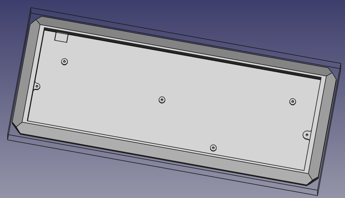
Here are a couple of pictures of my recreation:
Top-ish View:
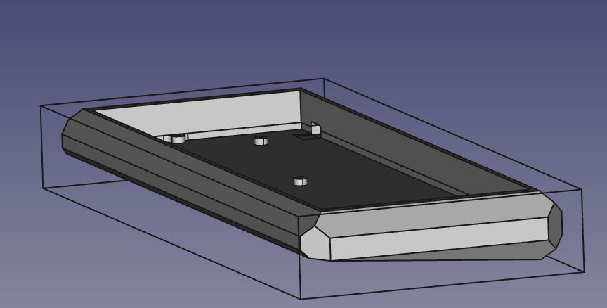
Side-ish View:
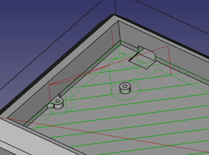
I had the idea of milling out the center area where the keyboard PCB and mounting plate would be placed and screwed in, preferably using the adaptive tool path, but every time I try to do this I can't find a way to finish the tops of the screw posts. A 2D adaptive tool path won't touch them of course, and the 3D Pocket tool doesn't cut the material down all the way. Attempting to finish them with a separate operation like a facing operation results in no generated paths when specifying one of the screw post's top faces. The algorithms for the various path operations also struggle with the slightly lower plane at the top left of the case pocket, and even when specifying that face in Adaptive or 3D pocket, it generates some interesting paths (but that isn't the end of the world, a couple of simple contour operations could clean that area up).
3D Pocket Path:
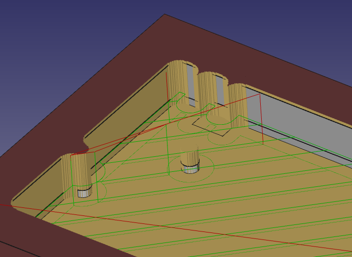
Simulation result of 3D Pocket:
My other main problem generating tool paths for this model is the big chamfers of the sides of the model. I have tried using the 3D surface operation and the waterline operation but I either don't know how to use them or they just aren't ready yet? All I get are paths that just go up and down on the Y-axis. I was hoping that I could create steps down the chamfers with a normal 3/8" endmill and then smooth them out with a 3/8" ball mill. If I can do that in FreeCAD then that would be great, especially since I want to sell stuff I make on my mill, and Fusion360 is out of the question because of that lol. I also like FreeCAD and open-source software in general! Any help would be appreciated. I also plan on trying to learn more about how tool path generation works and maybe contribute to the path workbench and maybe the libraries it depends on.
Edit: I am attaching the file. This case file is a recreation for academic/learning purposes and for helping the Path devs (maybe?). If you want the case you should go give KDBFans your money for one. I'd also like to mention that I am currently using FreeCAD 0.19 build 20900.
Sincerely,
Thorhian
I recreated an aluminum keyboard case as best as I could as a way to learn the basics of designing parts in FreeCAD. This case is the 5 Degree made by KDBFans (https://kbdfans.com/collections/60-layo ... -5-60-case). I have begun to get used to making parts in the part design workbench and I think I'll be using FreeCAD a lot now. However, I am trying to figure out how I could use the path workbench to create tool paths for a CNC Mill that I am in the process of making. I have used Fusion360 for CAM work so the process isn't totally foreign to me, but I'm no professional lol.
Here are a couple of pictures of my recreation:
Top-ish View:
Side-ish View:
I had the idea of milling out the center area where the keyboard PCB and mounting plate would be placed and screwed in, preferably using the adaptive tool path, but every time I try to do this I can't find a way to finish the tops of the screw posts. A 2D adaptive tool path won't touch them of course, and the 3D Pocket tool doesn't cut the material down all the way. Attempting to finish them with a separate operation like a facing operation results in no generated paths when specifying one of the screw post's top faces. The algorithms for the various path operations also struggle with the slightly lower plane at the top left of the case pocket, and even when specifying that face in Adaptive or 3D pocket, it generates some interesting paths (but that isn't the end of the world, a couple of simple contour operations could clean that area up).
3D Pocket Path:
Simulation result of 3D Pocket:
My other main problem generating tool paths for this model is the big chamfers of the sides of the model. I have tried using the 3D surface operation and the waterline operation but I either don't know how to use them or they just aren't ready yet? All I get are paths that just go up and down on the Y-axis. I was hoping that I could create steps down the chamfers with a normal 3/8" endmill and then smooth them out with a 3/8" ball mill. If I can do that in FreeCAD then that would be great, especially since I want to sell stuff I make on my mill, and Fusion360 is out of the question because of that lol. I also like FreeCAD and open-source software in general!
Edit: I am attaching the file. This case file is a recreation for academic/learning purposes and for helping the Path devs (maybe?). If you want the case you should go give KDBFans your money for one. I'd also like to mention that I am currently using FreeCAD 0.19 build 20900.
Sincerely,
Thorhian