Hole callouts

Discussions about the development of the TechDraw workbench
Forum rules
Be nice to others! Respect the FreeCAD code of conduct!
Post Reply
JulianStirling
Posts: 61
Joined: Sun May 29, 2016 2:19 pm
Contact:

Hole callouts

Post by JulianStirling »

I have been playing with TechDraw in v0.19 (I am not sure I am 100% up to speed as the PPA is not working for 20.04).

Tech draw has come on so far since it was first introduced. I used to take a lot of drawings to the workshop where I had to modify the technical drawing in inkscape.

A couple of things which I think would really be great and sound like low hanging fruit (but I have no idea) are:
  • being able to add a kink to diameter/radius dimensions.
  • Getting the full information from the hole call wizard, including the depth and counterbore/countersink
User avatar
wandererfan
Veteran
Posts: 6326
Joined: Tue Nov 06, 2012 5:42 pm
Contact:

Re: Hole callouts

Post by wandererfan »

JulianStirling wrote: Fri Jul 31, 2020 3:44 pm [*] being able to add a kink to diameter/radius dimensions.
Maybe use a different style? ISO Referencing and ASME Referencing styles have kinks. ISO Oriented and ASME Inlined styles have no kink.
[*] Getting the full information from the hole call wizard, including the depth and counterbore/countersink
I don't know much about the hole wizard.

I guess we would need a "hole annotation" function? Pick a circle on the drawing and a hole feature in the the tree and then make something like a balloon with the required information?

Is the information text only like this?
.4375 - 20UNF - 2A, LH
MJ6 x 1 - 4H5H
Or are there symbols required?
JulianStirling
Posts: 61
Joined: Sun May 29, 2016 2:19 pm
Contact:

Re: Hole callouts

Post by JulianStirling »

wandererfan wrote: Sun Aug 02, 2020 3:51 pm Maybe use a different style? ISO Referencing and ASME Referencing styles have kinks. ISO Oriented and ASME Inlined styles have no kink.
Fantastic, I probably need to read the docs more rather than wing it! Is there a way to change this on a per sheet basis rather than in global preferences?

wandererfan wrote: Sun Aug 02, 2020 3:51 pm I guess we would need a "hole annotation" function? Pick a circle on the drawing and a hole feature in the the tree and then make something like a balloon with the required information?

Is the information text only like this?
.4375 - 20UNF - 2A, LH
MJ6 x 1 - 4H5H
Or are there symbols required?
There are symbols required. All of the 4H, 5H, 6H stuff is really overkill. All holes are 6H unless specified and you really need to be doing quite specialised fitting before you get into that. Of course take that with a grain of salt because we all live in a bit of a bubble, maybe I just don't work with people that use it.

Generally the work I have done we do a lot of adapter plates for screwing things down, so holes are either clearance holes or tapped holes and some have a depth. The hole depth is set with the ↧ symbol (though in Technical Drawings it is normally much wider). The specifications for a counterbore are set with ⌴ and a countersink with ⌵ (in Technical Drawings these characters are normally full height).

So a tapped M6 blind hole that is 20mm deep would be
M6↧20
or if I want to be explicit on the pitch
M6x1↧20

A 6.3 mm hole that goes all the way through I would specify as
Ø6.3 THRU

If it was counterbored for M6 it might say
Ø6.3 THRU
⌴ Ø11.2↧6
meaning that the hole is diameter 6.3 mm and goes through but has a counterbore that is 11.2 mm diameter an 6 mm deep.


As an example from the internet here is a countersunk hole
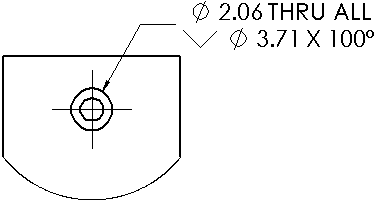
Image

And an example of a technical drawing with some counterbores:
Image
and the counterbore explained:
Image
chrisb
Veteran
Posts: 54301
Joined: Tue Mar 17, 2015 9:14 am

Re: Hole callouts

Post by chrisb »

JulianStirling wrote: Sun Aug 02, 2020 4:40 pm Fantastic, I probably need to read the docs more rather than wing it! Is there a way to change this on a per sheet basis rather than in global preferences?
You can change it per dimension. The values set in preferences are just default values.

That means they should be set in italics in the preferences.
A Sketcher Lecture with in-depth information is available in English, auf Deutsch, en français, en español.
JulianStirling
Posts: 61
Joined: Sun May 29, 2016 2:19 pm
Contact:

Re: Hole callouts

Post by JulianStirling »

chrisb wrote: Sun Aug 02, 2020 5:40 pm You can change it per dimension. The values set in preferences are just default values.
I was looking in the "Data" tab not the "View" tab. Silly me! Thanks.
Post Reply